README.md
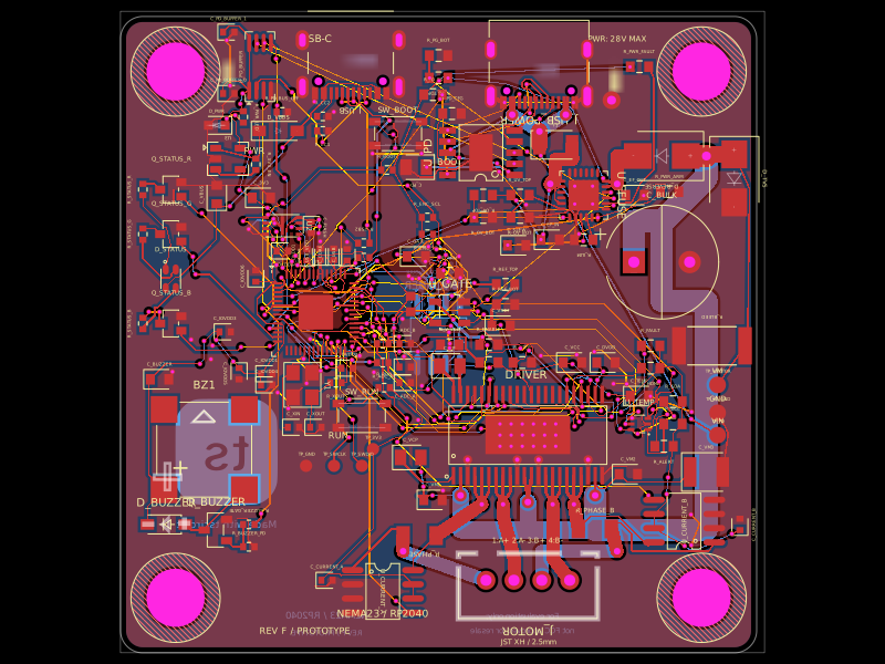
# NEMA8 20 mm dual-USB-C stepper controller

Four-layer 20 mm × 20 mm controller for the StepperOnline
[8HS15-0604S](https://www.omc-stepperonline.com/nema-8-bipolar-1-8deg-4ncm-5-7oz-in-0-6a-6v-20x20x38mm-4-wires-8hs15-0604s)
bipolar stepper motor (0.60 A/phase, 11 Ω, 5.5 mH).

## Architecture

- CH32X035F8U6 controller/USB-PD MCU and TMC2209-LA-T stepper driver.
- A top-side WS2812B-1313-V6 addressable RGB status LED on PA2, with its own local bottom-side 100 nF bypass capacitor. The selected V6 device is specified for the board's 3.3 V logic rail, and the emitter remains visible when the PCB is mounted to the motor.
- A top-side TMP102 PCB-temperature sensor on a two-wire bus (PA6/SDA and PA5/SCL), with 4.7 kΩ pull-ups, local 100 nF bypassing, and ADD0 tied to ground for address `0x48`. This measures board temperature independently of the TMC2209's internal overtemperature protection.
- Two matching top-entry/vertical USB-C receptacles: one dedicated to power/PD and one to USB data/programming.
- Each PWR / PD CC pin has its own 5.1 kΩ Rd pull-down to ground (R_PD_CC1 and R_PD_CC2, JLCPCB C25905), while both CC lines remain connected to the CH32X035 for PD negotiation.
- Both top-entry USB-C receptacles, the edge-facing motor connector, and the TMC2209 are on the top side; the MCU is on the bottom side.
- PWR / PD, DATA / PROG, BOOT, motor phase order, and motor current limit are marked in silkscreen.
- The three schematic sheets use functional net labels (`VM`, `VIO`, `USB_DP`, `STEP`, `DIR`, `ENN`, `VREF`, `SENSE_A/B`, and explicit motor phases), and the PCB trace inspector uses matching semantic identifiers instead of `ROUTE_n` names.
- Four 2.2 mm mounting holes on the motor's specified 15.4 mm square M2 pattern. A placement-only 2.35 mm-radius courtyard around every hole keeps fitted parts clear of the screw-head sweep on both board sides without blocking copper.
- A device-level `assembly.motor` preview models the 8HS15-0604S at its current published 20.3 mm maximum frame, 39.3 mm body, 10 mm × Ø4 mm D-shaft, and 15.4 mm fastener pattern. The PCB is centered on the motor back face with its bottom side toward the motor and a 4 mm clearance gap. The motor's JST-SH-4 cable side is rotated toward `J_MOTOR`, and `assembly.cable` renders the four-wire harness entering the board's top-entry motor connector vertically.
- Four copper layers with only full-stack plated through-vias; blind and buried vias are disabled.
- 0.30 mm via drills and 0.45 mm via pads.
- The corrected motor-phase route and the TMC2209 VS1-to-VS2 load-supply tie use only top/bottom copper; their existing current-carrying widths are preserved. The added low-current status/I²C signals use deterministic inner-layer channels only between full-stack through-vias.
- Default tscircuit autorouter and explicit JLCPCB/LCSC identifiers for fitted parts.
- 40 V-rated HT7533-1 3.3 V regulator on the logic rail, providing headroom above the 15 V USB-PD motor supply and its switching transients.
- The HT7533-1 now has dedicated local input and output bypass capacitors at its pins; the original rail capacitors remain fitted as distributed bulk capacitance.
- TMC2209 exposed-pad thermal-via field, 1.1 A resettable fuse, reverse-current diode, imported SMAJ16A TVS clamp (JLCPCB/LCSC C20419815), and 94 µF nominal VM bulk capacitance from two 47 µF/25 V capacitors.
- The TMC2209 has local VM, 5VOUT, and VCC_IO bypassing with short ground returns at the driver in addition to the board-level bulk capacitance.
- TMC2209 UART control permits firmware adjustment of run/hold current. The 12 kΩ/10 kΩ VREF divider produces about 2.27 V; with 330 mΩ sense resistors this limits full-scale RMS current to about 0.60 A for the selected motor.

## Verification

Run the release checks from this directory:

```sh
npm run typecheck
npm run build
bunx tsci check schematic-placement index.circuit.tsx
bunx tsci check
bunx tsci check shorts index.circuit.tsx --mode pcb
bunx tsci check shorts index.circuit.tsx --mode gerber
```

The generated board must report zero DRC failures and zero shorts before a release is pushed. The schematic-placement analysis currently reports only the pin-padding advisory produced by each untouched `standard="usb_c"` schematic symbol; shrinking those boxes to the suggested width creates an inner-label collision, so the standard symbols are intentionally retained. The board definition fixes the outline at 20 mm × 20 mm, disables blind/buried vias, and requires 0.30/0.45 mm through-vias.

## Production notes

- The four-hole mounting pattern matches the 8HS15-0604S drawing: 15.4 ± 0.15 mm centers and M2 hardware. Placement reserves a 2.35 mm radius at every hole: 2.00 mm nominal screw-head radius, 0.10 mm radial play in the 2.2 mm PCB hole, and 0.15 mm mounting-pattern tolerance. Use 4 mm spacers/standoffs because the design has bottom-side components.
- The assembly view deliberately includes the motor's rear screw heads and verifies board envelope, hole alignment, and the nominal 4 mm clearance. The official drawing specifies the shaft-face M2 threaded holes but does not define the rear face as a PCB mounting interface, so confirm the longer/replacement rear-fastener stack-up on the physical motor before committing mechanical hardware.
- Both USB-C receptacles use the same compact 12-contact, 48 V/5 A top-entry USB 2.0 part (JLCPCB/LCSC C5815189); cables plug perpendicular to the PCB.
- Both receptacles face upward from the top side. The DATA connector's 180° setting is only an in-plane pin rotation; it does not change the cable-entry direction.
- The four USB-C CC pull-down resistors use the same fitted 0402 JLCPCB/LCSC part C25905: R_PD_CC1/R_PD_CC2 on PWR / PD and R_DATA_CC1/R_DATA_CC2 on DATA / PROG.
- `C_VM_BULK1` and `C_VM_BULK2` are fitted 47 µF/25 V 1206 capacitors (JLCPCB/LCSC C50767273), providing 94 µF nominal VM bulk capacitance before DC-bias derating.
- Driver-local bypass parts are `C_VM_LOCAL` 100 nF/50 V 0402 (C525226), `C_5V` 2.2 µF/10 V 0402 (C107370), and `C_VIO_LOCAL` 100 nF/16 V 0201 (C18164586).
- Regulator-local bypass parts are `C_LDO_IN_LOCAL` 2.2 µF/25 V 0402 (C5246831) and `C_LDO_OUT` 1 µF/10 V 0201 (C48986257). The original distant output capacitor is retained as distributed rail capacitance and is named `C_3V3_BULK`.
- `D_VM_TVS` uses the imported exact C20419815 DO-214AC/SMA pad geometry and supplier 3D model; its anode reaches the ground plane through both adjacent bulk-capacitor ground branches.
- This design targets the bare 8HS15-0604S motor. `J_MOTOR` pins 1–4 follow the shared controller convention A+, A−, B+, B−. For this exact motor, the manufacturer assigns black, green, red, and blue respectively; verify the connector's pin-1 viewing direction when crimping the motor-specific JST-SH harness.
- TMC2209 DIAG/INDEX are intentionally not routed in this dense revision; STEP, DIR, ENN, STDBY, and single-wire UART are connected to the MCU.
- Status/temperature fitted parts are WS2812B-1313-V6 `D_STATUS` (JLCPCB/LCSC C52941388), TMP102AIDRLR `U_TEMP` (C99269), two 4.7 kΩ 0201 pull-ups `R_TEMP_SCL`/`R_TEMP_SDA` (C170207), and two 100 nF 0201 bypass capacitors `C_STATUS`/`C_TEMP` (C18164586). No buzzer is fitted.
- The autorouter uses short neck-downs at fine-pitch pads. The longest power runs retain their requested widths, but the generated trace-width advisories must be reviewed with the Gerbers before production.
- USB-PD negotiation firmware, regeneration clamping, USB signal integrity, assembly rotations, driver thermals, and the 0.60 A current limit still require first-article validation.
- The USB-C source cannot absorb motor regeneration. Avoid aggressive deceleration until VM transients have been measured on hardware.