README.md
## Schematic pin alignment — 1.12.2

The USB connector pin stems now meet their symbol boxes in both functional sheets. Only schematic display lengths changed; pin endpoints, wires, source connectivity, PCB geometry and the motor assembly geometry remain identical to 1.12.1. [Correction and preservation evidence](artifacts/schematic-pin-alignment/verification.json) · [Updated A4 schematic](artifacts/schematic-a4.pdf).

## Motor and hardware assembly preview

The 1.12.1 assembly rotates the motor’s fixed-wire outlet toward the board’s JST edge. Four colored leads take a short loop through insulated splices to a 28-AWG JST-SH pigtail. The SHR-04V-S plug seats in the BM04B-SRSS-TB header at the catalog’s 6.3 mm mated height. Pin order is black A+, green A−, red B+, blue B−. There is no motor-side socket.

[Assembly details](docs/top-assembly.md) · [Full assembly](artifacts/top-assembly/assembly-complete.png) · [JST connection](artifacts/top-assembly/assembly-jst-connection.png) · [Top view](artifacts/top-assembly/assembly-top.png) · [Native assembly JSON](assembly.circuit.json).

PCB geometry and fabrication files are preserved from 1.12.0; schematic pin display lengths were corrected in 1.12.2. Nominal CAD checks pass for conductor separation, component clearance and plug alignment. Rear motor retention and physical crimp/latch fit remain unverified.

# NEMA14_CH32X035G8U6 1.11.0

**CAD qualified for hardware-prototype publication and JLCPCB engineering/order review.** All 50 physical nets are connected. Native DRC reports zero errors and warnings. All 23 qualification checks ran: 22 returned zero; the remaining command returned component-orientation advice with zero placement DRC errors/warnings. Default and order-review CAM audits pass.

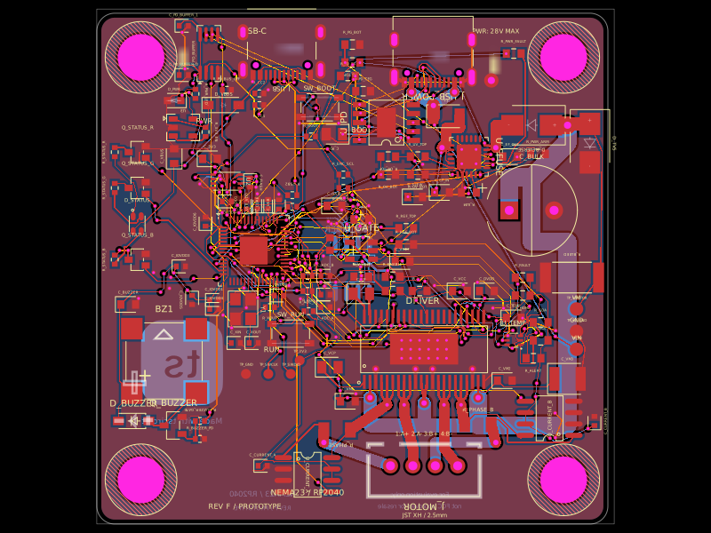
35 × 35 × 1.6 mm, four layers. Four NPTH mounting holes are exactly (±13, ±13), Ø3.2 mm in actual Circuit JSON and Excellon drills. Minimum via drill/pad is Ø0.30/Ø0.45 mm. Upright GCT USB4145 sockets occupy opposite edges; the defined 10 mm cable housings have 23.3 mm nominal clearance. The model screens maximum Ø6 × 3 mm screw heads within a Ø6.4 mm envelope and an Ø6 mm tool path.

All 61 fitted parts are TOP SMT. The bottom AS5600 and two capacitors are doNotPlace; six separate top test pads remain bare. Exact source components, ports, nets and traces match GitHub baseline a342a888. USB/PD, JST-SH A+/A−/B+/B− wiring, TMP102, status/power LEDs and buzzer are retained.

[Current review and checks](docs/opposite-edge-review.md) · [Qualification](artifacts/resume-validation.json) · [Connectivity](artifacts/physical-connectivity.json) · [JLCPCB review package](artifacts/jlcpcb-review/JLCPCB-OrderReview.zip) · [Six-sheet schematic PDF](artifacts/schematic-a4.pdf) · [Nominal mechanical screen](artifacts/mechanical/opposite-edge-fit.png).

Supplier stock, CPL pickup/polarity confirmation, thermal-via filling/capping, USB shell secondary soldering, and real cable/fastener tolerances need confirmation. Firmware, electrical/thermal bench testing, rear motor fit, and encoder shaft/magnet/air gap remain unverified. No order or payment was submitted.

Version 1.11.2 corrects generated order instructions, preview captions and the assembly concept for the opposite-edge upright USB-C arrangement. CPL guidance now uses the native land-pattern datum and requires supplier pickup confirmation. The qualified copper, footprints, drill files and frozen board hash are unchanged.