abse/museair-usb
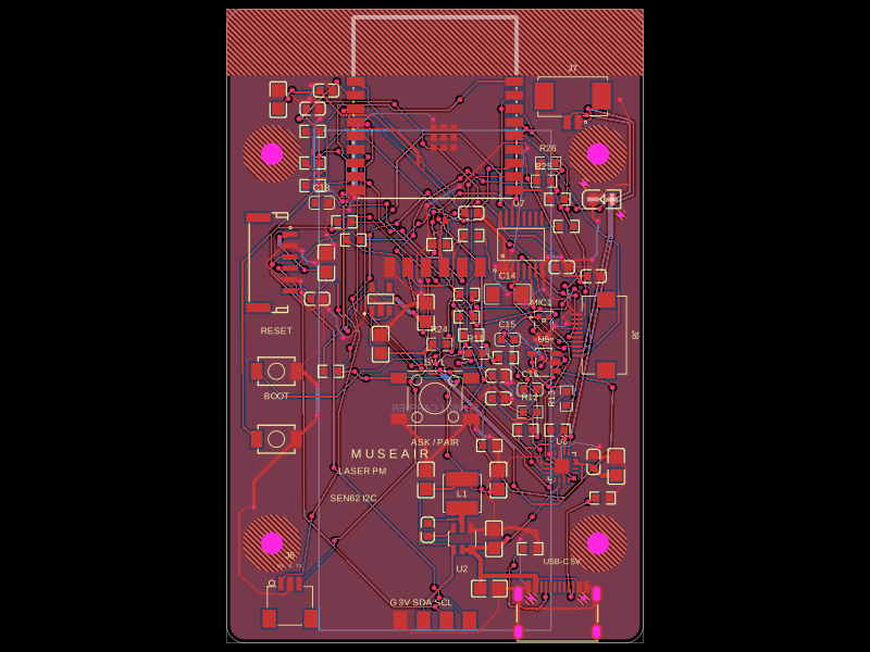
USB-C–powered ESP32-C3 controller board with AP63203 buck conversion, AP2112K 3.3V regulation, I²C SEN62 sensor interface, status LED, buttons, UART/I²C headers, and extensive decoupling.
- Version
- 0.5.7
- License
- unset
- Stars
- 0
index.circuit.tsx
PCB
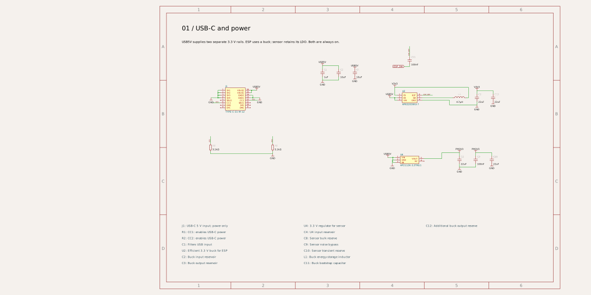
Schematic
import { TS_1102S_B_H_B } from "./imports/TS_1102S_B_H_B"
import { GRM31C5C1H104JA01L } from "./imports/GRM31C5C1H104JA01L"
import { GRM1885C1H103JA01D } from "./imports/GRM1885C1H103JA01D"
import { MAX98357AETE_T } from "./imports/MAX98357AETE_T"
import { ZTS6216 } from "./imports/ZTS6216"
import { TCA9534APWR } from "./imports/TCA9534APWR"
import { MCP6001T_I_OT } from "./imports/MCP6001T_I_OT"
import { AFC24_S10FIA_00 } from "./imports/AFC24_S10FIA_00"
import { A_532610271 } from "./imports/A_532610271"
import { A_0603WAF1003T5E } from "./imports/A_0603WAF1003T5E"
import { A_0603WAF1000T5E } from "./imports/A_0603WAF1000T5E"
import { A_0603WAF1004T5E } from "./imports/A_0603WAF1004T5E"
import React from "react"
import type { ResistorProps, CapacitorProps } from "@tscircuit/props"
import {ESP32C3, AP2112, USBC, SensorHeader, Button, StatusLED, R51, R10, R1, C1u0805, C10u, C22u, C100n, C1u0603} from "./components/JLCParts"

import { AP63203WU_7 } from "./imports/AP63203WU_7"
import { SWPA4030S4R7MT } from "./imports/SWPA4030S4R7MT"

import { ProgrammingHeader } from "./imports/ProgrammingHeader"

import { SEN62 } from "./components/SEN62"

// MuseAir USB v0.5. Soldered parts use exact JLCPCB/EasyEDA imports.
// U3 is the separate SEN62-SIN-T, retained under the PCB after reflow.
// J3 is a genuine JST GH-6 header for a verified one-to-one cable.
// USB-C is power only. J6 is the plug-in 3.3V UART header; J4 remains test pads.
const net=(s:string)=>`net.${s}`
const labels=(s:string[])=>Object.fromEntries(s.map((v,i)=>[`pin${i+1}`,v]))
const con=(s:Record<string,string>)=>Object.fromEntries(Object.entries(s).map(([k,v])=>[k,net(v)]))
const c=(a:string,b:string)=>con({pin1:a,pin2:b})
const R=(p:ResistorProps)=>{const Part=String(p.resistance)==="5.1k"?R51:String(p.resistance)==="10k"?R10:R1; return <Part {...p}/>}
const C=(p:CapacitorProps)=>{const Part=String(p.capacitance)==="100nF"?C100n:String(p.capacitance)==="10uF"?C10u:String(p.capacitance)==="22uF"?C22u:p.footprint==="0603"?C1u0603:C1u0805; const {footprint,...rest}=p; return <Part {...rest}/>}
export default ({routingDisabled=false}:{routingDisabled?:boolean}={})=>(
 <board schWidth={90} schHeight={65} title="MuseAir USB display/audio draft" width={46} height={70} borderRadius={2} layers={2} thickness={1.6}
 solderMaskColor="black" silkscreenColor="white" autorouter={{local:true,traceClearance:0.25}} autorouterEffortLevel="5x"
 routingDisabled={routingDisabled} minTraceWidth={0.15} nominalTraceWidth={0.2}
 minTraceToPadEdgeClearance={0.1} minPadEdgeToPadEdgeClearance={0.1} minBoardEdgeClearance={0.3}
 minViaHoleDiameter={0.3} minViaPadDiameter={0.6}
 pcbStyle={{silkscreenFontSize:0.7,silkscreenTextPosition:"none"}} schTraceAutoLabelEnabled schMaxTraceDistance={0.5} schAutoLayoutEnabled={false} schLayout={{layoutMode:"none"}}>
  <schematicsheet name="POWER" displayName="01 / USB-C and power" sheetIndex={1}>
  <schematictext schX={-14.3} schY={9.6} anchor="left" fontSize={0.5} text="01 / USB-C and power"/>
  <schematictext schX={-14.3} schY={8.5} anchor="left" fontSize={0.24} text="USB5V supplies two separate 3.3 V rails. ESP uses a buck; sensor retains its LDO. Both are always on."/>
  <schematictext schX={-14.3} schY={-6.3} anchor="left" fontSize={0.22} color="#36535f" text="J1: USB-C 5 V input; power only"/>
  <schematictext schX={-14.3} schY={-6.8} anchor="left" fontSize={0.22} color="#36535f" text="R1: CC1: enables USB-C power"/>
  <schematictext schX={-14.3} schY={-7.3} anchor="left" fontSize={0.22} color="#36535f" text="R2: CC2: enables USB-C power"/>
  <schematictext schX={-14.3} schY={-7.8} anchor="left" fontSize={0.22} color="#36535f" text="C1: Filters USB input"/>
  <schematictext schX={-14.3} schY={-8.3} anchor="left" fontSize={0.22} color="#36535f" text="U2: Efficient 3.3 V buck for ESP"/>
  <schematictext schX={-14.3} schY={-8.8} anchor="left" fontSize={0.22} color="#36535f" text="C2: Buck input reservoir"/>
  <schematictext schX={-14.3} schY={-9.3} anchor="left" fontSize={0.22} color="#36535f" text="C3: Buck output reservoir"/>
  <schematictext schX={-4.5} schY={-6.3} anchor="left" fontSize={0.22} color="#36535f" text="U4: 3.3 V regulator for sensor"/>
  <schematictext schX={-4.5} schY={-6.8} anchor="left" fontSize={0.22} color="#36535f" text="C4: U4 input reservoir"/>
  <schematictext schX={-4.5} schY={-7.3} anchor="left" fontSize={0.22} color="#36535f" text="C8: Sensor bulk reserve"/>
  <schematictext schX={-4.5} schY={-7.8} anchor="left" fontSize={0.22} color="#36535f" text="C9: Sensor noise bypass"/>
  <schematictext schX={-4.5} schY={-8.3} anchor="left" fontSize={0.22} color="#36535f" text="C10: Sensor transient reserve"/>
  <schematictext schX={-4.5} schY={-8.8} anchor="left" fontSize={0.22} color="#36535f" text="L1: Buck energy-storage inductor"/>
  <schematictext schX={-4.5} schY={-9.3} anchor="left" fontSize={0.22} color="#36535f" text="C11: Buck bootstrap capacitor"/>
  <schematictext schX={5.300000000000001} schY={-6.3} anchor="left" fontSize={0.22} color="#36535f" text="C12: Additional buck output reserve"/>
 </schematicsheet>
  <schematicsheet name="CONTROLLER" displayName="02 / ESP32 controller and boot" sheetIndex={2}>
  <schematictext schX={-14.3} schY={9.6} anchor="left" fontSize={0.5} text="02 / ESP32 controller and boot"/>
  <schematictext schX={-14.3} schY={8.5} anchor="left" fontSize={0.24} text="Antenna stays inside the PCB outline; top copper-free area must stay clear."/>
  <schematictext schX={-14.3} schY={-6.3} anchor="left" fontSize={0.22} color="#36535f" text="U1: Wi-Fi / BLE controller"/>
  <schematictext schX={-14.3} schY={-6.8} anchor="left" fontSize={0.22} color="#36535f" text="C5: ESP current reserve"/>
  <schematictext schX={-14.3} schY={-7.3} anchor="left" fontSize={0.22} color="#36535f" text="C6: ESP noise bypass"/>
  <schematictext schX={-14.3} schY={-7.8} anchor="left" fontSize={0.22} color="#36535f" text="R4: Keeps ESP enabled"/>
  <schematictext schX={-14.3} schY={-8.3} anchor="left" fontSize={0.22} color="#36535f" text="C7: Delays power-on reset"/>
  <schematictext schX={-14.3} schY={-8.8} anchor="left" fontSize={0.22} color="#36535f" text="R5: GPIO8 boot pullup"/>
  <schematictext schX={-14.3} schY={-9.3} anchor="left" fontSize={0.22} color="#36535f" text="R6: Normal-boot pullup"/>
  <schematictext schX={-4.5} schY={-6.3} anchor="left" fontSize={0.22} color="#36535f" text="R7: GPIO2 boot pullup"/>
  <schematictext schX={-4.5} schY={-6.8} anchor="left" fontSize={0.22} color="#36535f" text="SW2: Press to reset ESP"/>
  <schematictext schX={-4.5} schY={-7.3} anchor="left" fontSize={0.22} color="#36535f" text="SW3: Hold for flashing"/>
 </schematicsheet>
  <schematicsheet name="SENSOR" displayName="03 / Air sensor and I2C" sheetIndex={3}>
  <schematictext schX={-14.3} schY={9.6} anchor="left" fontSize={0.5} text="03 / Air sensor and I2C"/>
  <schematictext schX={-14.3} schY={8.5} anchor="left" fontSize={0.24} text="SDA = GPIO1; SCL = GPIO3. SEN62: address 0x6B, maximum 100 kHz."/>
  <schematictext schX={-14.3} schY={8.0} anchor="left" fontSize={0.24} text="U3 installs after reflow in the carrier, 4 mm below the PCB underside."/>
  <schematictext schX={-14.3} schY={7.5} anchor="left" fontSize={0.24} text="J3 cable: 1=3.3V, 2=GND, 3=SDA, 4=SCL, 5=GND, 6=3.3V; verify 1:1."/>
  <schematictext schX={-14.3} schY={-6.3} anchor="left" fontSize={0.22} color="#36535f" text="J3: GH-6 cable to SEN62"/>
  <schematictext schX={-14.3} schY={-6.8} anchor="left" fontSize={0.22} color="#36535f" text="R8: SDA idle-high pullup"/>
  <schematictext schX={-14.3} schY={-7.3} anchor="left" fontSize={0.22} color="#36535f" text="R9: SCL idle-high pullup"/>
  <schematictext schX={-14.3} schY={-7.8} anchor="left" fontSize={0.22} color="#36535f" text="J5: Optional I2C test pads"/>
  <schematictext schX={-14.3} schY={-8.3} anchor="left" fontSize={0.22} color="#36535f" text="U3: Laser PM, humidity and temperature"/>
 </schematicsheet>
  <schematicsheet name="INTERFACES" displayName="04 / Controls and programming" sheetIndex={4}>
  <schematictext schX={-14.3} schY={8.5} anchor="left" fontSize={0.24} text="J6: SH-3 straight-through cable to programmer J5. 1=RX, 2=GND, 3=TX; 3.3 V logic; USB-C power."/>
  <schematictext schX={-14.3} schY={9.6} anchor="left" fontSize={0.5} text="04 / Controls and programming"/>
  <schematictext schX={-14.3} schY={-6.3} anchor="left" fontSize={0.22} color="#36535f" text="J4: Optional UART test pads"/>
  <schematictext schX={-14.3} schY={-6.8} anchor="left" fontSize={0.22} color="#36535f" text="R3: ASK idle-high pullup"/>
  <schematictext schX={-14.3} schY={-7.3} anchor="left" fontSize={0.22} color="#36535f" text="SW1: Raised ASK / pair actuator"/>
  <schematictext schX={-14.3} schY={-7.8} anchor="left" fontSize={0.22} color="#36535f" text="R10: Limits LED current"/>
  <schematictext schX={-14.3} schY={-8.3} anchor="left" fontSize={0.22} color="#36535f" text="D1: Firmware status light"/>
  <schematictext schX={-14.3} schY={-8.8} anchor="left" fontSize={0.22} color="#36535f" text="TPG1: Ground probe point"/>
  <schematictext schX={-14.3} schY={-9.3} anchor="left" fontSize={0.22} color="#36535f" text="TPG2: Ground probe point"/>
  <schematictext schX={-4.5} schY={-6.3} anchor="left" fontSize={0.22} color="#36535f" text="TPG3: Ground probe point"/>
  <schematictext schX={-4.5} schY={-6.8} anchor="left" fontSize={0.22} color="#36535f" text="J6: Plug-in SH-3 UART programmer"/>
 </schematicsheet>
  <schematicsheet name="MICROPHONE" displayName="05 / Top-port microphone and ADC" sheetIndex={5}>
  <schematictext schX={-14.3} schY={9.6} anchor="left" fontSize={0.5} text="05 / Top-port microphone and ADC"/>
  <schematictext schX={-14.3} schY={-6.3} anchor="left" fontSize={0.22} color="#36535f" text="MIC1: Top-port MEMS microphone, 65 dBA SNR"/>
  <schematictext schX={-14.3} schY={-6.8} anchor="left" fontSize={0.22} color="#36535f" text="U5: Microphone preamp, gain 51"/>
  <schematictext schX={-14.3} schY={-7.3} anchor="left" fontSize={0.22} color="#36535f" text="R11: Filters microphone supply"/>
  <schematictext schX={-14.3} schY={-7.8} anchor="left" fontSize={0.22} color="#36535f" text="C13: Microphone supply reservoir"/>
  <schematictext schX={-14.3} schY={-8.3} anchor="left" fontSize={0.22} color="#36535f" text="C14: C0G microphone bypass, 100 nF"/>
  <schematictext schX={-14.3} schY={-8.8} anchor="left" fontSize={0.22} color="#36535f" text="C15: C0G microphone DC blocking"/>
  <schematictext schX={-14.3} schY={-9.3} anchor="left" fontSize={0.22} color="#36535f" text="C16: Parallel C0G microphone coupling"/>
  <schematictext schX={-4.5} schY={-6.3} anchor="left" fontSize={0.22} color="#36535f" text="R12: Biases microphone preamp input"/>
  <schematictext schX={-4.5} schY={-6.8} anchor="left" fontSize={0.22} color="#36535f" text="R13: Preamp feedback, 100 kohm"/>
  <schematictext schX={-4.5} schY={-7.3} anchor="left" fontSize={0.22} color="#36535f" text="R14: Preamp gain resistor, first 1 kohm"/>
  <schematictext schX={-4.5} schY={-7.8} anchor="left" fontSize={0.22} color="#36535f" text="R15: Preamp gain resistor, second 1 kohm"/>
  <schematictext schX={-4.5} schY={-8.3} anchor="left" fontSize={0.22} color="#36535f" text="R16: Bias divider upper resistor"/>
  <schematictext schX={-4.5} schY={-8.8} anchor="left" fontSize={0.22} color="#36535f" text="R17: Bias divider middle resistor"/>
  <schematictext schX={-4.5} schY={-9.3} anchor="left" fontSize={0.22} color="#36535f" text="R18: Bias divider lower resistor"/>
  <schematictext schX={5.300000000000001} schY={-6.3} anchor="left" fontSize={0.22} color="#36535f" text="C17: Filters microphone bias"/>
  <schematictext schX={5.300000000000001} schY={-6.8} anchor="left" fontSize={0.22} color="#36535f" text="R19: ADC input filter, 5.1 kohm"/>
  <schematictext schX={5.300000000000001} schY={-7.3} anchor="left" fontSize={0.22} color="#36535f" text="C18: C0G ADC filter, 10 nF"/>
 </schematicsheet>
  <schematicsheet name="SPEAKER" displayName="06 / Speaker amplifier and JST lead" sheetIndex={6}>
  <schematictext schX={-14.3} schY={9.6} anchor="left" fontSize={0.5} text="06 / Speaker amplifier and JST lead"/>
  <schematictext schX={-14.3} schY={-6.3} anchor="left" fontSize={0.22} color="#36535f" text="U6: I2S class D speaker amplifier"/>
  <schematictext schX={-14.3} schY={-6.8} anchor="left" fontSize={0.22} color="#36535f" text="C19: Speaker amplifier local bypass"/>
  <schematictext schX={-14.3} schY={-7.3} anchor="left" fontSize={0.22} color="#36535f" text="C20: Speaker amplifier current reserve"/>
  <schematictext schX={-14.3} schY={-7.8} anchor="left" fontSize={0.22} color="#36535f" text="J7: PicoBlade speaker plug, both pins driven"/>
  <schematictext schX={-14.3} schY={-8.3} anchor="left" fontSize={0.22} color="#36535f" text="R22: Keeps amplifier muted at boot"/>
 </schematicsheet>
  <schematicsheet name="DISPLAY" displayName="07 / Colour display and I2C controls" sheetIndex={7}>
  <schematictext schX={-14.3} schY={9.6} anchor="left" fontSize={0.5} text="07 / Colour display and I2C controls"/>
  <schematictext schX={-14.3} schY={-6.3} anchor="left" fontSize={0.22} color="#36535f" text="U7: I2C slow controls, address 0x38"/>
  <schematictext schX={-14.3} schY={-6.8} anchor="left" fontSize={0.22} color="#36535f" text="C21: Expander local bypass"/>
  <schematictext schX={-14.3} schY={-7.3} anchor="left" fontSize={0.22} color="#36535f" text="R20: Keeps display deselected at boot"/>
  <schematictext schX={-14.3} schY={-7.8} anchor="left" fontSize={0.22} color="#36535f" text="R21: Keeps display reset released"/>
  <schematictext schX={-14.3} schY={-8.3} anchor="left" fontSize={0.22} color="#36535f" text="J8: 10-pin 0.5 mm dual-contact display ZIF"/>
  <schematictext schX={-14.3} schY={-8.8} anchor="left" fontSize={0.22} color="#36535f" text="C22: Display supply local bypass"/>
  <schematictext schX={-14.3} schY={-9.3} anchor="left" fontSize={0.22} color="#36535f" text="C23: Display supply reserve"/>
  <schematictext schX={-4.5} schY={-6.3} anchor="left" fontSize={0.22} color="#36535f" text="R24: Backlight limit, parallel resistor 1"/>
  <schematictext schX={-4.5} schY={-6.8} anchor="left" fontSize={0.22} color="#36535f" text="R25: Backlight limit, parallel resistor 2"/>
  <schematictext schX={-4.5} schY={-7.3} anchor="left" fontSize={0.22} color="#36535f" text="R26: Backlight limit, parallel resistor 3"/>
 </schematicsheet>
 {/* Route with extra clearance margin, then check against the 0.1 mm design limit. */}
 <autoroutingphase minTraceToPadEdgeClearance={0.3} minPadEdgeToPadEdgeClearance={0.3}/>

 <net name="USB5V" isPowerNet nominalTraceWidth={0.5}/>
 <net name="PM3V3" isPowerNet nominalTraceWidth={0.5}/>
 <net name="V3V3" isPowerNet nominalTraceWidth={0.5}/>
 <net name="GND" isGroundNet nominalTraceWidth={0.35}/>

 <ESP32C3 name="U1" schHeight={2} schSheetName="CONTROLLER" pcbX={0} pcbY={21} schX={0} schY={2.94}
 manufacturerPartNumber="ESP32-C3-WROOM-02-N4" supplierPartNumbers={{jlcpcb:["C2934560"]}}
 pinLabels={labels(["V3V3","EN","ASK","SPARE5","SPARE6","SPARE7","STRAP8","BOOT","GND","STATUS","UART_RX","UART_TX","USB_DM","USB_DP","SCL","STRAP2","SDA","SPARE0","EP"])}
 connections={con({V3V3:"V3V3",EN:"EN",ASK:"ASK",STRAP8:"STRAP8",BOOT:"BOOT",GND:"GND",STATUS:"STATUS",UART_RX:"UART_RX",UART_TX:"UART_TX",SCL:"SCL",STRAP2:"STRAP2",SDA:"SDA",SPARE5:"AUDIO_BCLK",SPARE6:"AUDIO_WS",SPARE7:"AUDIO_DIN",USB_DM:"LCD_SCLK",USB_DP:"LCD_MOSI",SPARE0:"MIC_ADC",EP:"GND"})}
 pinAttributes={{V3V3:{requiresPower:true,requiresVoltage:3.3,shouldHaveDecouplingCapacitor:true},GND:{requiresGround:true},EP:{requiresGround:true},EN:{mustBeConnected:true},ASK:{isGpio:true,needsExternalPullup:true},STRAP8:{needsExternalPullup:true},BOOT:{needsExternalPullup:true},STRAP2:{needsExternalPullup:true}}}
/>

 <USBC name="J1" schSheetName="POWER" pcbX={13.5} pcbY={-31.0} shouldBeOnEdgeOfBoard schX={-10} schY={3.9}
 manufacturerPartNumber="TYPE-C-31-M-12" supplierPartNumbers={{jlcpcb:["C165948"]}}
 pinLabels={labels(["SH1","SH2","SH3","SH4","SBU2","CC1","DM2","DP1","DM1","DP2","SBU1","CC2","GND1","GND2","VBUS1","VBUS2"])}
 connections={con({SH1:"GND",SH2:"GND",SH3:"GND",SH4:"GND",GND2:"GND",CC1:"CC1",CC2:"CC2"})}
 pinAttributes={{GND1:{providesGround:true},GND2:{providesGround:true},VBUS1:{providesPower:true,providesVoltage:5},VBUS2:{providesPower:true,providesVoltage:5}}}
 noConnect={["SBU1","SBU2","DM1","DM2","DP1","DP2"]}/>
 <trace from=".J1 > .VBUS1" to="net.USB5V" thickness={0.5}/>
 <trace from=".J1 > .GND1" to="net.GND" thickness={0.35}/>
 {/* Keep the USB power fan-out above the fine-pitch pins and locating holes. */}
 <trace name="USB_FANOUT" from=".J1 > .VBUS2" to=".C1 > .pin1" thickness={0.5}
 pcbPath={[{x:-2.3999571,y:3.4},{x:-8.5,y:3.4}]}/>
 <R name="R1" schOrientation="vertical" schSheetName="POWER" resistance="5.1k" pcbX={10.5} pcbY={-24.6} schX={-12} schY={2.22045e-16} connections={c("CC1","GND")}/>
 <R name="R2" schOrientation="vertical" schSheetName="POWER" resistance="5.1k" pcbX={18.5} pcbY={-19} schX={-7} schY={2.22045e-16} connections={c("CC2","GND")}/>
 <C name="C1" schOrientation="vertical" schSheetName="POWER" capacitance="1uF" pcbX={6} pcbY={-29.0} schX={-3} schY={6} connections={c("USB5V","GND")}/>

 <AP63203WU_7 name="U2" schSheetName="POWER" pcbX={3} pcbY={-23.5} schX={4} schY={4}
 connections={con({VIN:"USB5V",EN:"USB5V",GND:"GND",FB:"V3V3",SW:"ESP_SW",BST:"ESP_BST"})}
 pinAttributes={{pin1:{mustBeConnected:true},pin2:{mustBeConnected:true},pin3:{requiresPower:true,requiresVoltage:5},pin4:{requiresGround:true},pin5:{mustBeConnected:true},pin6:{mustBeConnected:true},VIN:{requiresPower:true,requiresVoltage:5,shouldHaveDecouplingCapacitor:true},GND:{requiresGround:true},EN:{mustBeConnected:true},FB:{mustBeConnected:true},SW:{mustBeConnected:true},BST:{mustBeConnected:true}}}/>
 <net name="ESP_SW" nominalTraceWidth={0.6}/>
 <net name="ESP_BST" nominalTraceWidth={0.2}/>
 <SWPA4030S4R7MT name="L1" schSheetName="POWER" pcbX={3} pcbY={-18.5} pcbRotation={90} schX={8} schY={4}
 connections={c("ESP_SW","V3V3")}/>
 <trace name="ESP_SWITCH_NODE" from=".U2 > .SW" to=".L1 > .pin1" thickness={0.6}/>
 <C name="C11" schOrientation="vertical" schSheetName="POWER" capacitance="100nF" footprint="0603" pcbX={-0.8} pcbY={-22.5} pcbRotation={90} schX={4} schY={7} connections={c("ESP_BST","ESP_SW")}/>
 <C name="C2" schOrientation="vertical" schSheetName="POWER" capacitance="10uF" pcbX={6.5} pcbY={-23.5} pcbRotation={90} schX={-1.7} schY={6} connections={c("USB5V","GND")}/>
 <C name="C3" schOrientation="vertical" schSheetName="POWER" capacitance="22uF" pcbX={7} pcbY={-17} pcbRotation={90} schX={9.4} schY={4} connections={c("V3V3","GND")}/>
 <C name="C12" schOrientation="vertical" schSheetName="POWER" capacitance="22uF" pcbX={-1} pcbY={-17} pcbRotation={90} schX={10.7} schY={4} connections={c("V3V3","GND")}/>
 <C name="C4" schOrientation="vertical" schSheetName="POWER" capacitance="10uF" pcbX={-6} pcbY={-2} pcbRotation={90} schX={-0.4} schY={6} connections={c("USB5V","GND")}/>
 <R name="R3" schOrientation="vertical" schSheetName="INTERFACES" resistance="10k" pcbX={-11.5} pcbY={-5} schX={4} schY={4} connections={c("V3V3","ASK")}/>
 <TS_1102S_B_H_B name="SW1" schSheetName="INTERFACES" pcbX={0} pcbY={-8} schX={10} schY={4}
 internallyConnectedPins={[["pin1","pin2"],["pin3","pin4"]]}
 connections={con({pin1:"ASK",pin2:"ASK",pin3:"GND",pin4:"GND"})}/>
 <C name="C5" schOrientation="vertical" schSheetName="CONTROLLER" capacitance="22uF" pcbX={-17.3} pcbY={25} pcbRotation={90} schX={-8} schY={6} connections={c("V3V3","GND")}/>
 <C name="C6" schOrientation="vertical" schSheetName="CONTROLLER" capacitance="100nF" footprint="0603" pcbX={-12} pcbY={26} schX={-6.7} schY={6} connections={c("V3V3","GND")}/>
 <R name="R4" schOrientation="vertical" schSheetName="CONTROLLER" resistance="10k" pcbX={-13.5} pcbY={21.5} schX={-8} schY={0} connections={c("V3V3","EN")}/>
 <C name="C7" schOrientation="vertical" schSheetName="CONTROLLER" capacitance="1uF" footprint="0603" pcbX={-13.5} pcbY={24} schX={-8} schY={-3} connections={c("EN","GND")}/>
 <R name="R5" schOrientation="vertical" schSheetName="CONTROLLER" resistance="10k" pcbX={-13.5} pcbY={18} schX={6} schY={6} connections={c("V3V3","STRAP8")}/>
 <R name="R6" schOrientation="vertical" schSheetName="CONTROLLER" resistance="10k" pcbX={-13.5} pcbY={15.5} schX={9} schY={6} connections={c("V3V3","BOOT")}/>
 <R name="R7" schOrientation="vertical" schSheetName="CONTROLLER" resistance="10k" pcbX={14.5} pcbY={11.0} schX={12} schY={6} connections={c("V3V3","STRAP2")}/>
 <Button name="SW2" schRotation={-90} schSheetName="CONTROLLER" pcbX={-17.5} pcbY={-5} schX={-4} schY={-3.18} manufacturerPartNumber="TS-1088-AR02016" supplierPartNumbers={{jlcpcb:["C720477"]}}
 pinLabels={labels(["A","B"])} connections={con({A:"EN",B:"GND"})}/>
 <Button name="SW3" schRotation={-90} schSheetName="CONTROLLER" pcbX={-17.5} pcbY={-12.5} schX={4} schY={-3.18} manufacturerPartNumber="TS-1088-AR02016" supplierPartNumbers={{jlcpcb:["C720477"]}}
 pinLabels={labels(["A","B"])} connections={con({A:"BOOT",B:"GND"})}/>
 <SensorHeader name="J3" schSheetName="SENSOR" pcbX={-18} pcbY={7} pcbRotation={-90} schX={-6} schY={3.5}
 pinLabels={labels(["VDD1","GND1","SDA","SCL","GND2","VDD2","SH1","SH2"])}
 connections={con({VDD1:"PM3V3",GND1:"GND",SDA:"SDA",SCL:"SCL",GND2:"GND",VDD2:"PM3V3"})}
 pinAttributes={{VDD1:{requiresPower:true,requiresVoltage:3.3},GND1:{requiresGround:true},VDD2:{requiresPower:true,requiresVoltage:3.3},GND2:{requiresGround:true}}}
 noConnect={["SH1","SH2"]}/>
 {/* I2C pullups are on the ESP rail; both regulators always power up together. */}
 <R name="R8" schOrientation="vertical" schSheetName="SENSOR" resistance="10k" pcbX={-10} pcbY={11.5} schX={-2} schY={5} connections={c("V3V3","SDA")}/>
 <R name="R9" schOrientation="vertical" schSheetName="SENSOR" resistance="10k" pcbX={-9} pcbY={9.5} schX={1} schY={5} connections={c("V3V3","SCL")}/>
 <AP2112 name="U4" schHeight={0.6} schSheetName="POWER" pcbX={-6} pcbY={3} schX={4} schY={-1}
 pinLabels={labels(["VIN","GND","EN","NC","VOUT"])}
 pinAttributes={{VIN:{requiresPower:true,requiresVoltage:5,shouldHaveDecouplingCapacitor:true},GND:{requiresGround:true},EN:{mustBeConnected:true},NC:{doNotConnect:true},VOUT:{providesPower:true,providesVoltage:3.3}}}
 connections={con({VIN:"USB5V",GND:"GND",EN:"USB5V"})} noConnect={["NC"]}/>
 <trace from=".U4 > .VOUT" to="net.PM3V3" thickness={0.5}/>
 <C name="C8" schOrientation="vertical" schSheetName="POWER" capacitance="22uF" pcbX={-12} pcbY={7} pcbRotation={90} schX={8} schY={-1} connections={c("PM3V3","GND")}/>
 <C name="C9" schOrientation="vertical" schSheetName="POWER" capacitance="100nF" footprint="0603" pcbX={-13} pcbY={3} schX={9.3} schY={-1} connections={c("PM3V3","GND")}/>
 <C name="C10" schOrientation="vertical" schSheetName="POWER" capacitance="22uF" pcbX={-1} pcbY={1.5} pcbRotation={90} schX={10.6} schY={-1} connections={c("PM3V3","GND")}/>
 <R name="R10" schSheetName="INTERFACES" resistance="1k" pcbX={13.5} pcbY={14} schX={4} schY={-2} connections={c("STATUS","LED_STATUS")}/>
 <StatusLED name="D1" schRotation={-90} schSheetName="INTERFACES" color="green" pcbX={18.5} pcbY={14} schX={10} schY={-2} connections={{anode:net("LED_STATUS"),cathode:net("GND")}}/>
 <connector name="J4" schSheetName="INTERFACES" doNotPlace pcbX={0} pcbY={6.5} schX={-6} schY={4}
 manufacturerPartNumber="UART 6-pin pogo/solder contacts, 2mm pitch" pinLabels={labels(["GND","V3V3","TX","RX","BOOT","EN"])}
 footprint={<footprint insertionDirection="from_above">
 {[0,1,2,3,4,5].map(i=><smtpad portHints={[`pin${i+1}`]} pcbX={(i-2.5)*2} pcbY={0} width={1.2} height={2.2} shape="rect"/>)}
 <courtyardrect pcbX={0} pcbY={0} width={11.6} height={2.6}/>
 </footprint>}
 connections={con({GND:"GND",V3V3:"V3V3",TX:"UART_TX",RX:"UART_RX",BOOT:"BOOT",EN:"EN"})}/>
 <ProgrammingHeader name="J6" schSheetName="INTERFACES" pcbX={-16} pcbY={-30.5} schX={-7.5} schY={-1.8}
 uartSilkscreenLabels={["RX","G","TX"]}
 pinLabels={{pin1:["RX"],pin2:["GND"],pin3:["TX"]}}
 connections={con({RX:"UART_RX",GND:"GND",TX:"UART_TX"})}/>
 <connector name="J5" schSheetName="SENSOR" doNotPlace pcbX={0} pcbY={-32.5} schX={6} schY={-3}
 manufacturerPartNumber="I2C 4-pin solder contacts, 2.54mm pitch" pinLabels={labels(["GND","V3V3","SDA","SCL"])}
 footprint={<footprint insertionDirection="from_above">
 {[0,1,2,3].map(i=><smtpad portHints={[`pin${i+1}`]} pcbX={(i-1.5)*2.54} pcbY={0} width={1.5} height={2} shape="rect"/>)}
 <courtyardrect pcbX={0} pcbY={0} width={9.5} height={2.4}/>
 </footprint>}
 connections={con({GND:"GND",V3V3:"V3V3",SDA:"SDA",SCL:"SCL"})}/>
 {/* Added top-side display/audio. The expander is only for slow controls;
     SPI and I2S clocks remain native ESP GPIO. ADC1 GPIO0 works with Wi-Fi. */}
 <ZTS6216 name="MIC1" schSheetName="MICROPHONE" pcbX={12} pcbY={0} schX={-4} schY={3}
 connections={con({OUT:"MIC_RAW",GND1:"GND",GND2:"GND",VDD:"MIC3V3"})}/>
 <MCP6001T_I_OT name="U5" schHeight={0.6} schSheetName="MICROPHONE" pcbX={12.0} pcbY={-4.0} schX={3} schY={3}
 connections={con({VOUT:"MIC_AMP",VSS:"GND",VIN_POS:"MIC_AC",VIN_NEG:"MIC_FB",VDD:"MIC3V3"})}/>
 <A_0603WAF1000T5E name="R11" schOrientation="vertical" schSheetName="MICROPHONE" pcbX={4.5} pcbY={-3.0} schX={-4} schY={6} connections={c("V3V3","MIC3V3")}/>
 <C name="C13" schOrientation="vertical" capacitance="1uF" footprint="0603" schSheetName="MICROPHONE" pcbX={7.0} pcbY={-5.5} schX={-2} schY={6} connections={c("MIC3V3","GND")}/>
 <GRM31C5C1H104JA01L name="C14" schOrientation="vertical" schSheetName="MICROPHONE" pcbX={8.0} pcbY={3.5} schX={-0.7} schY={6} connections={c("MIC3V3","GND")}/>
 <GRM1885C1H103JA01D name="C15" schOrientation="vertical" schSheetName="MICROPHONE" pcbX={8.0} pcbY={-1.5} schX={-2} schY={3.5} connections={c("MIC_RAW","MIC_AC")}/>
 <GRM1885C1H103JA01D name="C16" schOrientation="vertical" schSheetName="MICROPHONE" pcbX={10.5} pcbY={-7.0} schX={-0.5} schY={3.5} connections={c("MIC_RAW","MIC_AC")}/>
 <A_0603WAF1004T5E name="R12" schOrientation="vertical" schSheetName="MICROPHONE" pcbX={10.5} pcbY={-9.5} schX={-2} schY={1} connections={c("MIC_AC","MIC_BIAS")}/>
 <A_0603WAF1003T5E name="R13" schSheetName="MICROPHONE" pcbX={14.5} pcbY={-8.0} pcbRotation={90} schX={3} schY={6.5} connections={c("MIC_AMP","MIC_FB")}/>
 <R name="R14" resistance="1k" schSheetName="MICROPHONE" pcbX={13.5} pcbY={-11.5} schX={3} schY={-0.5} connections={c("MIC_FB","MIC_RG")}/>
 <R name="R15" resistance="1k" schSheetName="MICROPHONE" pcbX={10.0} pcbY={-11.5} schX={3} schY={-3} connections={c("MIC_RG","MIC_BIAS")}/>
 <R name="R16" schOrientation="vertical" resistance="10k" schSheetName="MICROPHONE" pcbX={4.0} pcbY={-1.0} schX={-5} schY={1.2} connections={c("MIC3V3","MIC_DIV")}/>
 <R name="R17" schOrientation="vertical" resistance="10k" schSheetName="MICROPHONE" pcbX={7.8} pcbY={-3.5} schX={-5} schY={-0.8} connections={c("MIC_DIV","MIC_BIAS")}/>
 <R name="R18" schOrientation="vertical" resistance="10k" schSheetName="MICROPHONE" pcbX={6.0} pcbY={-13.2} schX={-5} schY={-2.8} connections={c("MIC_BIAS","GND")}/>
 <C name="C17" schOrientation="vertical" capacitance="1uF" footprint="0603" schSheetName="MICROPHONE" pcbX={7.0} pcbY={-8.0} schX={-2} schY={-0.8} connections={c("MIC_BIAS","GND")}/>
 <R name="R19" resistance="5.1k" schSheetName="MICROPHONE" pcbX={3.5} pcbY={1.0} schX={7} schY={3} connections={c("MIC_AMP","MIC_ADC")}/>
 <GRM1885C1H103JA01D name="C18" schOrientation="vertical" schSheetName="MICROPHONE" pcbX={-12.5} pcbY={13.6} schX={7} schY={0} connections={c("MIC_ADC","GND")}/>
 <MAX98357AETE_T name="U6" schWidth={2.53} schHeight={1.8} schSheetName="SPEAKER" pcbX={14.0} pcbY={-15.5} schX={-3} schY={2}
 connections={con({DIN:"AUDIO_DIN",GAIN_SLOT:"USB5V",GND1:"GND",N_SD_MODE:"AMP_ENABLE",VDD1:"USB5V",VDD2:"USB5V",OUTP:"SPK_P",OUTN:"SPK_N",GND2:"GND",LRCLK:"AUDIO_WS",GND3:"GND",BCLK:"AUDIO_BCLK",EP:"GND"})}
 noConnect={["pin5","pin6","pin12","pin13"]}/>
 <C name="C19" schOrientation="vertical" capacitance="100nF" footprint="0603" schSheetName="SPEAKER" pcbX={17.5} pcbY={-15.0} pcbRotation={90} schX={-7} schY={6} connections={c("USB5V","GND")}/>
 <C name="C20" schOrientation="vertical" capacitance="10uF" schSheetName="SPEAKER" pcbX={20.0} pcbY={-15.5} pcbRotation={90} schX={-5.7} schY={6} connections={c("USB5V","GND")}/>
 <A_532610271 name="J7" schSheetName="SPEAKER" pcbX={15.2} pcbY={24.3} pcbRotation={0} schX={6} schY={2}
 connections={con({pin1:"SPK_P",pin2:"SPK_N"})} noConnect={["pin3","pin4"]}/>
 <TCA9534APWR name="U7" schSheetName="DISPLAY" pcbX={9.5} pcbY={9.0} schX={-7} schY={2}
 connections={con({A0:"GND",A1:"GND",A2:"GND",P0:"LCD_CS",P1:"LCD_DC",P2:"LCD_RESET",P3:"AMP_ENABLE",GND:"GND",SCL:"SCL",SDA:"SDA",VCC:"V3V3"})}
 noConnect={["P4","P5","P6","P7","N_INT"]}/>
 <C name="C21" schOrientation="vertical" capacitance="100nF" footprint="0603" schSheetName="DISPLAY" pcbX={4.0} pcbY={12.5} schX={-2} schY={6} connections={c("V3V3","GND")}/>
 <R name="R20" schOrientation="vertical" resistance="10k" schSheetName="DISPLAY" pcbX={4.0} pcbY={10.0} schX={-4} schY={5} connections={c("V3V3","LCD_CS")}/>
 <R name="R21" schOrientation="vertical" resistance="10k" schSheetName="DISPLAY" pcbX={3.5} pcbY={3.5} schX={-2} schY={3} connections={c("V3V3","LCD_RESET")}/>
 <R name="R22" schRotation={90} resistance="1k" schSheetName="SPEAKER" pcbX={0.5} pcbY={9.0} schX={-3} schY={-3} connections={c("GND","AMP_ENABLE")}/>
 <AFC24_S10FIA_00 name="J8" schSheetName="DISPLAY" pcbX={17.5} pcbY={-1} pcbRotation={-90} schX={5} schY={2}
 connections={con({pin1:"LCD_MOSI",pin2:"LCD_SCLK",pin3:"LCD_DC",pin4:"LCD_RESET",pin5:"LCD_CS",pin7:"V3V3",pin8:"GND",pin9:"LCD_LEDA",pin10:"GND"})}
 noConnect={["pin6","pin11","pin12"]}/>
 <C name="C22" schOrientation="vertical" capacitance="100nF" footprint="0603" schSheetName="DISPLAY" pcbX={17.5} pcbY={5.5} schX={-0.7} schY={6} connections={c("V3V3","GND")}/>
 <C name="C23" schOrientation="vertical" capacitance="1uF" footprint="0603" schSheetName="DISPLAY" pcbX={14.0} pcbY={6.5} schX={0.6} schY={6} connections={c("V3V3","GND")}/>

 <A_0603WAF1000T5E name="R24" schOrientation="vertical" schSheetName="DISPLAY" pcbX={0.5} pcbY={-2.0} schX={7} schY={-2} connections={c("USB5V","LCD_LEDA")}/>
 <A_0603WAF1000T5E name="R25" schOrientation="vertical" schSheetName="DISPLAY" pcbX={12.0} pcbY={16.0} schX={9} schY={-2} connections={c("USB5V","LCD_LEDA")}/>
 <A_0603WAF1000T5E name="R26" schOrientation="vertical" schSheetName="DISPLAY" pcbX={12.5} pcbY={18.0} schX={11} schY={-2} connections={c("USB5V","LCD_LEDA")}/>
 <SEN62 name="U3" schSheetName="SENSOR" pcbX={0} pcbY={-6} schX={-6} schY={-3}/>
 <keepout shape="circle" pcbX={-18} pcbY={-24} radius={3.2} layers={["top","bottom"]} excludeRefs={[".U3"]}/>
 <keepout shape="circle" pcbX={18} pcbY={-24} radius={3.2} layers={["top","bottom"]} excludeRefs={[".U3"]}/>
 <keepout shape="circle" pcbX={-18} pcbY={19} radius={3.2} layers={["top","bottom"]} excludeRefs={[".U3"]}/>
 <keepout shape="circle" pcbX={18} pcbY={19} radius={3.2} layers={["top","bottom"]} excludeRefs={[".U3"]}/>

 {/* Reserve the entire board width under and beside the internal antenna. */}
 <keepout shape="rect" pcbX={0} pcbY={31.325} width={46} height={7.35} layers={["top","bottom"]} excludeRefs={[".U1"]}/>
 <keepout shape="circle" pcbX={10.600082} pcbY={-30.0944328} radius={0.7} layers={["top","bottom"]} excludeRefs={[".J1"]}/>
 <keepout shape="circle" pcbX={16.399918} pcbY={-30.0944328} radius={0.7} layers={["top","bottom"]} excludeRefs={[".J1"]}/>
 <copperpour connectsTo="net.GND" layer="top" clearance={0.2} boardEdgeMargin={0.4}/>
 <copperpour connectsTo="net.GND" layer="bottom" clearance={0.2} boardEdgeMargin={0.4}/>
 {[[-20,-20],[20.4,25],[12,4]].map(([x,y],i)=><connector name={`TPG${i+1}`} key={i} doNotPlace pcbX={x} pcbY={y} schSheetName="INTERFACES" schX={-9+i*5} schY={-5.5} pinLabels={{pin1:["GND"]}} connections={{GND:net("GND")}} footprint={<footprint insertionDirection="from_above"><platedhole portHints={["pin1"]} holeDiameter={0.3} outerDiameter={0.6} shape="circle"/><courtyardrect width={0.9} height={0.9}/></footprint>}/>)}
 <silkscreentext pcbX={-5} pcbY={-14.1} text="M U S E A I R" fontSize={1.4}/>
 <silkscreentext pcbX={0} pcbY={-12.8} text="ASK / PAIR" fontSize={1}/>
 <silkscreentext pcbX={14} pcbY={-26} text="USB-C 5V" fontSize={0.9}/>
 {/* J4 test-pad pin names remain on schematic sheet 4; keep crowded silk clear. */}
 <silkscreentext pcbX={-1.5} pcbY={-30.5} text="G 3V SDA SCL" fontSize={1}/>
 <silkscreentext pcbX={-9} pcbY={-19} text="SEN62 I2C" fontSize={1}/>
 <silkscreentext pcbX={-8} pcbY={-16} text="LASER PM" fontSize={1}/>
 <silkscreentext pcbX={-17.5} pcbY={-.5} text="RESET" fontSize={1}/>
 <silkscreentext pcbX={-17.5} pcbY={-7.7} text="BOOT" fontSize={1}/>
 <silkscreentext pcbX={0} pcbY={-9} layer="bottom" text="SEN62 / CARRIER" fontSize={1.1}/>
 {/* Bivar VLP-350-F: two NPTH press-fit pins, Bivar VLP-XXX-X rev L.
     Assembly XY maps to PCB (worldY, 2.5-worldX); 0.30 mm copper clearance. */}
 {[ [20.532,12.2728], [16.468,15.7272] ].map(([x,y],i)=><React.Fragment key={`lightpipe-${i}`}>
   <hole diameter={0.6096} pcbX={x} pcbY={y}/>
   <keepout shape="circle" pcbX={x} pcbY={y} radius={0.6048} layers={["top","bottom"]} excludeRefs={[".U3"]}/>
 </React.Fragment>)}
 </board>
)
Related Packages
 More from this authorabse/dual-usb-peltier-assemblyA USB‑C PD Peltier controller PCB combining RP2040 control, adjustable buck‑boost TEC power, temperature sensing, fan regulation, USB programming, protection, status LEDs, and external accessory hardware.
 Similar packagemohan-bee/esp32-c3This hardware design integrates an ESP32-C3 microcontroller, a USB-C connector, a power management IC (AP2112-3.3V regulator), a USB-to-Serial converter (CH340C), several resistors, capacitors, and user-accessible headers to facilitate USB communication, power regulation, and general I/O interfacing.
 Discover something new0hmX/mt41k512m8da-107-it-p-fanoutThis code defines the physical footprint, routing, and layout configuration for a DDR3 memory module using surface-mount pads, vias, and copper traces on a printed circuit board (PCB).