pixalynx/cm5-minimal-carrier
A 4-layer Raspberry Pi CM5 carrier board routes USB‑C 5V power through an RT9742 load switch with TVS protection and capacitive filtering, while providing ESD-protected HDMI output, CM5 connectors, test points, and ground/power planes.
- Version
- 0.1.1
- License
- unset
- Stars
- 0
references/cm5-datasheet.txt
Raspberry Pi | Raspberry Pi Compute Module 5 Datasheet
Raspberry Pi
Compute Module 5
A Raspberry Pi for deeply embedded
applications
Raspberry Pi Ltd
Raspberry Pi Compute Module 5
Colophon
©︎ 2022-2026 Raspberry Pi Ltd
This documentation is licensed under a Creative Commons Attribution-NoDerivatives 4.0 International (CC BY-ND).
Release 3
Build date 08/06/2026
Legal disclaimer notice
TECHNICAL AND RELIABILITY DATA FOR RASPBERRY PI PRODUCTS (INCLUDING DATASHEETS) AS MODIFIED FROM TIME TO
TIME (“RESOURCES”) ARE PROVIDED BY RASPBERRY PI LTD (“RPL”) “AS IS” AND ANY EXPRESS OR IMPLIED WARRANTIES,
INCLUDING, BUT NOT LIMITED TO, THE IMPLIED WARRANTIES OF MERCHANTABILITY AND FITNESS FOR A PARTICULAR
PURPOSE ARE DISCLAIMED. TO THE MAXIMUM EXTENT PERMITTED BY APPLICABLE LAW IN NO EVENT SHALL RPL BE LIABLE
FOR ANY DIRECT, INDIRECT, INCIDENTAL, SPECIAL, EXEMPLARY, OR CONSEQUENTIAL DAMAGES (INCLUDING, BUT NOT LIMITED
TO, PROCUREMENT OF SUBSTITUTE GOODS OR SERVICES; LOSS OF USE, DATA, OR PROFITS; OR BUSINESS INTERRUPTION)
HOWEVER CAUSED AND ON ANY THEORY OF LIABILITY, WHETHER IN CONTRACT, STRICT LIABILITY, OR TORT (INCLUDING
NEGLIGENCE OR OTHERWISE) ARISING IN ANY WAY OUT OF THE USE OF THE RESOURCES, EVEN IF ADVISED OF THE POSSIBILITY
OF SUCH DAMAGE.
RPL reserves the right to make any enhancements, improvements, corrections or any other modifications to the RESOURCES or
any products described in them at any time and without further notice.
The RESOURCES are intended for skilled users with suitable levels of design knowledge. Users are solely responsible for their
selection and use of the RESOURCES and any application of the products described in them. User agrees to indemnify and hold
RPL harmless against all liabilities, costs, damages or other losses arising out of their use of the RESOURCES.
RPL grants users permission to use the RESOURCES solely in conjunction with the Raspberry Pi products. All other use of the
RESOURCES is prohibited. No licence is granted to any other RPL or other third party intellectual property right.
HIGH RISK ACTIVITIES. Raspberry Pi products are not designed, manufactured or intended for use in hazardous environments
requiring fail safe performance, such as in the operation of nuclear facilities, aircraft navigation or communication systems, air
traffic control, weapons systems or safety-critical applications (including life support systems and other medical devices), in which
the failure of the products could lead directly to death, personal injury or severe physical or environmental damage (“High Risk
Activities”). RPL specifically disclaims any express or implied warranty of fitness for High Risk Activities and accepts no liability
for use or inclusions of Raspberry Pi products in High Risk Activities.
Raspberry Pi products are provided subject to RPL’s Standard Terms. RPL’s provision of the RESOURCES does not expand or
otherwise modify RPL’s Standard Terms including but not limited to the disclaimers and warranties expressed in them.
Colophon 1
Raspberry Pi Compute Module 5
Table of Contents
1. Introduction . . . . . . . . . . . . . . . . . . . . . . . . . . . . . . . . . . . . . . . . . . . . . . . . . . . . . . . . . . . . . . . . . . . . . . . . . . . . . . . . . . . . . . . . . . . . . . . . . . . . . . . . . . . . . . . . . . . . . . 4
1.1. Connectors . . . . . . . . . . . . . . . . . . . . . . . . . . . . . . . . . . . . . . . . . . . . . . . . . . . . . . . . . . . . . . . . . . . . . . . . . . . . . . . . . . . . . . . . . . . . . . . . . . . . . . . . . . . . . . . . 4
1.2. Compatibility . . . . . . . . . . . . . . . . . . . . . . . . . . . . . . . . . . . . . . . . . . . . . . . . . . . . . . . . . . . . . . . . . . . . . . . . . . . . . . . . . . . . . . . . . . . . . . . . . . . . . . . . . . . . . . 4
1.3. Features . . . . . . . . . . . . . . . . . . . . . . . . . . . . . . . . . . . . . . . . . . . . . . . . . . . . . . . . . . . . . . . . . . . . . . . . . . . . . . . . . . . . . . . . . . . . . . . . . . . . . . . . . . . . . . . . . . . 5
2. Interfaces . . . . . . . . . . . . . . . . . . . . . . . . . . . . . . . . . . . . . . . . . . . . . . . . . . . . . . . . . . . . . . . . . . . . . . . . . . . . . . . . . . . . . . . . . . . . . . . . . . . . . . . . . . . . . . . . . . . . . . . . 6
2.1. Wireless . . . . . . . . . . . . . . . . . . . . . . . . . . . . . . . . . . . . . . . . . . . . . . . . . . . . . . . . . . . . . . . . . . . . . . . . . . . . . . . . . . . . . . . . . . . . . . . . . . . . . . . . . . . . . . . . . . . 6
2.1.1. Wi-Fi disable ( WL_nDisable ) . . . . . . . . . . . . . . . . . . . . . . . . . . . . . . . . . . . . . . . . . . . . . . . . . . . . . . . . . . . . . . . . . . . . . . . . . . . . . . . . . . . . . . . . 6
2.1.2. Bluetooth disable ( BT_nDisable ) . . . . . . . . . . . . . . . . . . . . . . . . . . . . . . . . . . . . . . . . . . . . . . . . . . . . . . . . . . . . . . . . . . . . . . . . . . . . . . . . . . . 6
2.2. Ethernet . . . . . . . . . . . . . . . . . . . . . . . . . . . . . . . . . . . . . . . . . . . . . . . . . . . . . . . . . . . . . . . . . . . . . . . . . . . . . . . . . . . . . . . . . . . . . . . . . . . . . . . . . . . . . . . . . . . 7
2.2.1. Connector and design guidance . . . . . . . . . . . . . . . . . . . . . . . . . . . . . . . . . . . . . . . . . . . . . . . . . . . . . . . . . . . . . . . . . . . . . . . . . . . . . . . . . . . . 7
2.2.2. Status LEDs and sync output . . . . . . . . . . . . . . . . . . . . . . . . . . . . . . . . . . . . . . . . . . . . . . . . . . . . . . . . . . . . . . . . . . . . . . . . . . . . . . . . . . . . . . . 7
2.3. PCIe Gen 2 . . . . . . . . . . . . . . . . . . . . . . . . . . . . . . . . . . . . . . . . . . . . . . . . . . . . . . . . . . . . . . . . . . . . . . . . . . . . . . . . . . . . . . . . . . . . . . . . . . . . . . . . . . . . . . . . 8
2.3.1. Routing guidance . . . . . . . . . . . . . . . . . . . . . . . . . . . . . . . . . . . . . . . . . . . . . . . . . . . . . . . . . . . . . . . . . . . . . . . . . . . . . . . . . . . . . . . . . . . . . . . . . . . 8
2.3.2. Required signals . . . . . . . . . . . . . . . . . . . . . . . . . . . . . . . . . . . . . . . . . . . . . . . . . . . . . . . . . . . . . . . . . . . . . . . . . . . . . . . . . . . . . . . . . . . . . . . . . . . . 8
2.4. USB interfaces . . . . . . . . . . . . . . . . . . . . . . . . . . . . . . . . . . . . . . . . . . . . . . . . . . . . . . . . . . . . . . . . . . . . . . . . . . . . . . . . . . . . . . . . . . . . . . . . . . . . . . . . . . . . 8
2.4.1. USB 3.0 (SuperSpeed) . . . . . . . . . . . . . . . . . . . . . . . . . . . . . . . . . . . . . . . . . . . . . . . . . . . . . . . . . . . . . . . . . . . . . . . . . . . . . . . . . . . . . . . . . . . . . . 8
2.4.2. USB 2.0 (High-Speed) . . . . . . . . . . . . . . . . . . . . . . . . . . . . . . . . . . . . . . . . . . . . . . . . . . . . . . . . . . . . . . . . . . . . . . . . . . . . . . . . . . . . . . . . . . . . . . 8
2.5. Video and display interfaces . . . . . . . . . . . . . . . . . . . . . . . . . . . . . . . . . . . . . . . . . . . . . . . . . . . . . . . . . . . . . . . . . . . . . . . . . . . . . . . . . . . . . . . . . . . . . . 9
2.5.1. Dual HDMI 2.0 . . . . . . . . . . . . . . . . . . . . . . . . . . . . . . . . . . . . . . . . . . . . . . . . . . . . . . . . . . . . . . . . . . . . . . . . . . . . . . . . . . . . . . . . . . . . . . . . . . . . . . 9
2.5.2. MIPI (CSI and DSI) . . . . . . . . . . . . . . . . . . . . . . . . . . . . . . . . . . . . . . . . . . . . . . . . . . . . . . . . . . . . . . . . . . . . . . . . . . . . . . . . . . . . . . . . . . . . . . . . . . 9
2.6. I2C interfaces . . . . . . . . . . . . . . . . . . . . . . . . . . . . . . . . . . . . . . . . . . . . . . . . . . . . . . . . . . . . . . . . . . . . . . . . . . . . . . . . . . . . . . . . . . . . . . . . . . . . . . . . . . . . 10
2.6.1. MIPI I2C bus ( SDA0 and SCL0 ) . . . . . . . . . . . . . . . . . . . . . . . . . . . . . . . . . . . . . . . . . . . . . . . . . . . . . . . . . . . . . . . . . . . . . . . . . . . . . . . . . . . . . 10
2.6.2. HAT EEPROM identification I2C bus ( ID_SD and ID_SC ) . . . . . . . . . . . . . . . . . . . . . . . . . . . . . . . . . . . . . . . . . . . . . . . . . . . . . . . . . . 10
2.7. SDIO (CM5Lite only) . . . . . . . . . . . . . . . . . . . . . . . . . . . . . . . . . . . . . . . . . . . . . . . . . . . . . . . . . . . . . . . . . . . . . . . . . . . . . . . . . . . . . . . . . . . . . . . . . . . . . 10
2.8. Debug UART . . . . . . . . . . . . . . . . . . . . . . . . . . . . . . . . . . . . . . . . . . . . . . . . . . . . . . . . . . . . . . . . . . . . . . . . . . . . . . . . . . . . . . . . . . . . . . . . . . . . . . . . . . . . . . 11
2.9. GPIO . . . . . . . . . . . . . . . . . . . . . . . . . . . . . . . . . . . . . . . . . . . . . . . . . . . . . . . . . . . . . . . . . . . . . . . . . . . . . . . . . . . . . . . . . . . . . . . . . . . . . . . . . . . . . . . . . . . . . 11
2.9.1. Alternative function assignments . . . . . . . . . . . . . . . . . . . . . . . . . . . . . . . . . . . . . . . . . . . . . . . . . . . . . . . . . . . . . . . . . . . . . . . . . . . . . . . . . 11
2.9.2. Alternative GPIO functions . . . . . . . . . . . . . . . . . . . . . . . . . . . . . . . . . . . . . . . . . . . . . . . . . . . . . . . . . . . . . . . . . . . . . . . . . . . . . . . . . . . . . . . . 12
2.9.3. Camera GPIOs ( CAM_GPIO ) . . . . . . . . . . . . . . . . . . . . . . . . . . . . . . . . . . . . . . . . . . . . . . . . . . . . . . . . . . . . . . . . . . . . . . . . . . . . . . . . . . . . . . . . 13
2.10. Status LEDs ( LED_nACT and LED_nPWR ) . . . . . . . . . . . . . . . . . . . . . . . . . . . . . . . . . . . . . . . . . . . . . . . . . . . . . . . . . . . . . . . . . . . . . . . . . . . . . . . . . . 13
2.11. Fan control ( Fan_PWM and Fan_Tacho ) . . . . . . . . . . . . . . . . . . . . . . . . . . . . . . . . . . . . . . . . . . . . . . . . . . . . . . . . . . . . . . . . . . . . . . . . . . . . . . . . . . . 13
2.12. Power management and control . . . . . . . . . . . . . . . . . . . . . . . . . . . . . . . . . . . . . . . . . . . . . . . . . . . . . . . . . . . . . . . . . . . . . . . . . . . . . . . . . . . . . . . 13
2.12.1. USB-C signals ( CC0 and CC1 ) . . . . . . . . . . . . . . . . . . . . . . . . . . . . . . . . . . . . . . . . . . . . . . . . . . . . . . . . . . . . . . . . . . . . . . . . . . . . . . . . . . . . . 13
2.12.2. System control signals ( PMIC_EN , PWR_BUT , VBAT , nRPI_BOOT , and EEPROM_nWP ) . . . . . . . . . . . . . . . . . . . . . . . . . . . . . . . . . . . 14
3. Power . . . . . . . . . . . . . . . . . . . . . . . . . . . . . . . . . . . . . . . . . . . . . . . . . . . . . . . . . . . . . . . . . . . . . . . . . . . . . . . . . . . . . . . . . . . . . . . . . . . . . . . . . . . . . . . . . . . . . . . . . . . 15
3.1. Power-up sequencing . . . . . . . . . . . . . . . . . . . . . . . . . . . . . . . . . . . . . . . . . . . . . . . . . . . . . . . . . . . . . . . . . . . . . . . . . . . . . . . . . . . . . . . . . . . . . . . . . . . . 15
3.2. Power-down sequencing . . . . . . . . . . . . . . . . . . . . . . . . . . . . . . . . . . . . . . . . . . . . . . . . . . . . . . . . . . . . . . . . . . . . . . . . . . . . . . . . . . . . . . . . . . . . . . . . . 15
3.3. Power consumption . . . . . . . . . . . . . . . . . . . . . . . . . . . . . . . . . . . . . . . . . . . . . . . . . . . . . . . . . . . . . . . . . . . . . . . . . . . . . . . . . . . . . . . . . . . . . . . . . . . . . 15
3.4. Regulator outputs . . . . . . . . . . . . . . . . . . . . . . . . . . . . . . . . . . . . . . . . . . . . . . . . . . . . . . . . . . . . . . . . . . . . . . . . . . . . . . . . . . . . . . . . . . . . . . . . . . . . . . . . 15
4. Specifications . . . . . . . . . . . . . . . . . . . . . . . . . . . . . . . . . . . . . . . . . . . . . . . . . . . . . . . . . . . . . . . . . . . . . . . . . . . . . . . . . . . . . . . . . . . . . . . . . . . . . . . . . . . . . . . . . . . 16
4.1. Mechanical specifications . . . . . . . . . . . . . . . . . . . . . . . . . . . . . . . . . . . . . . . . . . . . . . . . . . . . . . . . . . . . . . . . . . . . . . . . . . . . . . . . . . . . . . . . . . . . . . . 16
4.1.1. PCB dimensions . . . . . . . . . . . . . . . . . . . . . . . . . . . . . . . . . . . . . . . . . . . . . . . . . . . . . . . . . . . . . . . . . . . . . . . . . . . . . . . . . . . . . . . . . . . . . . . . . . 16
4.1.2. Wireless antenna . . . . . . . . . . . . . . . . . . . . . . . . . . . . . . . . . . . . . . . . . . . . . . . . . . . . . . . . . . . . . . . . . . . . . . . . . . . . . . . . . . . . . . . . . . . . . . . . . . 17
4.2. Pinout . . . . . . . . . . . . . . . . . . . . . . . . . . . . . . . . . . . . . . . . . . . . . . . . . . . . . . . . . . . . . . . . . . . . . . . . . . . . . . . . . . . . . . . . . . . . . . . . . . . . . . . . . . . . . . . . . . . . 17
4.2.1. Pin guidelines . . . . . . . . . . . . . . . . . . . . . . . . . . . . . . . . . . . . . . . . . . . . . . . . . . . . . . . . . . . . . . . . . . . . . . . . . . . . . . . . . . . . . . . . . . . . . . . . . . . . . 22
4.2.2. Differential pairs . . . . . . . . . . . . . . . . . . . . . . . . . . . . . . . . . . . . . . . . . . . . . . . . . . . . . . . . . . . . . . . . . . . . . . . . . . . . . . . . . . . . . . . . . . . . . . . . . . 23
4.3. Electrical specifications . . . . . . . . . . . . . . . . . . . . . . . . . . . . . . . . . . . . . . . . . . . . . . . . . . . . . . . . . . . . . . . . . . . . . . . . . . . . . . . . . . . . . . . . . . . . . . . . . 25
4.3.1. Absolute maximum ratings . . . . . . . . . . . . . . . . . . . . . . . . . . . . . . . . . . . . . . . . . . . . . . . . . . . . . . . . . . . . . . . . . . . . . . . . . . . . . . . . . . . . . . . 25
4.3.2. DC characteristics . . . . . . . . . . . . . . . . . . . . . . . . . . . . . . . . . . . . . . . . . . . . . . . . . . . . . . . . . . . . . . . . . . . . . . . . . . . . . . . . . . . . . . . . . . . . . . . . 25
4.3.3. Current consumption . . . . . . . . . . . . . . . . . . . . . . . . . . . . . . . . . . . . . . . . . . . . . . . . . . . . . . . . . . . . . . . . . . . . . . . . . . . . . . . . . . . . . . . . . . . . . 26
4.4. Thermal characteristics . . . . . . . . . . . . . . . . . . . . . . . . . . . . . . . . . . . . . . . . . . . . . . . . . . . . . . . . . . . . . . . . . . . . . . . . . . . . . . . . . . . . . . . . . . . . . . . . . . 27
4.5. Mean time between failure (MTBF) . . . . . . . . . . . . . . . . . . . . . . . . . . . . . . . . . . . . . . . . . . . . . . . . . . . . . . . . . . . . . . . . . . . . . . . . . . . . . . . . . . . . . . 27
5. Troubleshooting . . . . . . . . . . . . . . . . . . . . . . . . . . . . . . . . . . . . . . . . . . . . . . . . . . . . . . . . . . . . . . . . . . . . . . . . . . . . . . . . . . . . . . . . . . . . . . . . . . . . . . . . . . . . . . . . 28
5.1. Hardware power rails . . . . . . . . . . . . . . . . . . . . . . . . . . . . . . . . . . . . . . . . . . . . . . . . . . . . . . . . . . . . . . . . . . . . . . . . . . . . . . . . . . . . . . . . . . . . . . . . . . . . 28
Table of Contents 2
Raspberry Pi Compute Module 5
5.2. Bootloader firmware . . . . . . . . . . . . . . . . . . . . . . . . . . . . . . . . . . . . . . . . . . . . . . . . . . . . . . . . . . . . . . . . . . . . . . . . . . . . . . . . . . . . . . . . . . . . . . . . . . . . . 28
5.3. EEPROM management and firmware updates . . . . . . . . . . . . . . . . . . . . . . . . . . . . . . . . . . . . . . . . . . . . . . . . . . . . . . . . . . . . . . . . . . . . . . . . . . . 28
6. Ordering information . . . . . . . . . . . . . . . . . . . . . . . . . . . . . . . . . . . . . . . . . . . . . . . . . . . . . . . . . . . . . . . . . . . . . . . . . . . . . . . . . . . . . . . . . . . . . . . . . . . . . . . . . . . 29
6.1. Order quantity and packaging . . . . . . . . . . . . . . . . . . . . . . . . . . . . . . . . . . . . . . . . . . . . . . . . . . . . . . . . . . . . . . . . . . . . . . . . . . . . . . . . . . . . . . . . . . . 29
6.2. Part number codes . . . . . . . . . . . . . . . . . . . . . . . . . . . . . . . . . . . . . . . . . . . . . . . . . . . . . . . . . . . . . . . . . . . . . . . . . . . . . . . . . . . . . . . . . . . . . . . . . . . . . . 29
6.3. Product variants . . . . . . . . . . . . . . . . . . . . . . . . . . . . . . . . . . . . . . . . . . . . . . . . . . . . . . . . . . . . . . . . . . . . . . . . . . . . . . . . . . . . . . . . . . . . . . . . . . . . . . . . . 29
Appendix A. Test Points . . . . . . . . . . . . . . . . . . . . . . . . . . . . . . . . . . . . . . . . . . . . . . . . . . . . . . . . . . . . . . . . . . . . . . . . . . . . . . . . . . . . . . . . . . . . . . . . . . . . . . . . . . . 31
A.1. Test point map . . . . . . . . . . . . . . . . . . . . . . . . . . . . . . . . . . . . . . . . . . . . . . . . . . . . . . . . . . . . . . . . . . . . . . . . . . . . . . . . . . . . . . . . . . . . . . . . . . . . . . . . . . . 31
A.2. Test point connections for power and programming . . . . . . . . . . . . . . . . . . . . . . . . . . . . . . . . . . . . . . . . . . . . . . . . . . . . . . . . . . . . . . . . . . . . 33
Appendix B. CM4 and CM5 differences . . . . . . . . . . . . . . . . . . . . . . . . . . . . . . . . . . . . . . . . . . . . . . . . . . . . . . . . . . . . . . . . . . . . . . . . . . . . . . . . . . . . . . . . . . . 34
B.1. Pinout changes . . . . . . . . . . . . . . . . . . . . . . . . . . . . . . . . . . . . . . . . . . . . . . . . . . . . . . . . . . . . . . . . . . . . . . . . . . . . . . . . . . . . . . . . . . . . . . . . . . . . . . . . . . 34
B.1.1. Per-pin differences . . . . . . . . . . . . . . . . . . . . . . . . . . . . . . . . . . . . . . . . . . . . . . . . . . . . . . . . . . . . . . . . . . . . . . . . . . . . . . . . . . . . . . . . . . . . . . . . 34
B.1.2. Summary of functional and hardware changes . . . . . . . . . . . . . . . . . . . . . . . . . . . . . . . . . . . . . . . . . . . . . . . . . . . . . . . . . . . . . . . . . . . 35
B.2. Track lengths . . . . . . . . . . . . . . . . . . . . . . . . . . . . . . . . . . . . . . . . . . . . . . . . . . . . . . . . . . . . . . . . . . . . . . . . . . . . . . . . . . . . . . . . . . . . . . . . . . . . . . . . . . . . 35
B.3. Power budget . . . . . . . . . . . . . . . . . . . . . . . . . . . . . . . . . . . . . . . . . . . . . . . . . . . . . . . . . . . . . . . . . . . . . . . . . . . . . . . . . . . . . . . . . . . . . . . . . . . . . . . . . . . . 35
Appendix C. Documentation history . . . . . . . . . . . . . . . . . . . . . . . . . . . . . . . . . . . . . . . . . . . . . . . . . . . . . . . . . . . . . . . . . . . . . . . . . . . . . . . . . . . . . . . . . . . . . . . 36
Table of Contents 3
Raspberry Pi Compute Module 5
1. Introduction
Raspberry Pi Compute Module 5 (CM5) is a System on Module (SoM) designed to deliver the functionality of Raspberry Pi in a
compact and flexible form factor suited to embedded and industrial applications. It enables developers and system designers to
leverage the Raspberry Pi hardware and software stack in their own custom systems and designs.
CM5 includes a processor, memory (RAM), eMMC flash storage, and supporting power circuitry. It also provides I/O interfaces
beyond those available on standard Raspberry Pi boards, offering expanded options for more complex systems and designs.
Figure 1.
The front (left) and back (right) of Raspberry Pi Compute Module 5 (CM5)
For support documentation for CM5, see the Compute Module section of https://www.raspberrypi.com. You can also post a
question to the Forum.
1.1. Connectors
CM5 includes two 100-pin high-density connectors, providing access to nearly all CM5 interfaces. Together, these connectors
transmit power, data, and control signals to a carrier board. The top connector on CM5 contains pins 1 to 100; the bottom connector
of CM5 contains pins 101 to 200. For information about each pin’s assignment, see Section 4.2. Pinout.
CM5 has a companion carrier board, the Raspberry Pi Compute Module 5 IO Board (CM5IO) board, which is designed to expose and
enable CM5 interfaces. You can also design your own carrier board based on the CM5IO board. The CM5IO design files are freely
available. For detailed specifications and pinout information about CM5IO, see the Compute Module 5 IO board documentation.
1.2. Compatibility
CM5 and CM5Lite are mostly compatible with the previous generation of Compute Module. This means that CM5 can be used
in many existing designs and carrier boards with minimal changes. For a list of specific differences between CM5 and CM4, see
Appendix B. CM4 and CM5 differences.
Note
The previous generation of Compute Module (CM4) is still for sale and will remain in production until at least January 2034.
CM5 connects to carrier boards through its two 100-pin connectors. The main change in the pin layout (pinout) compared to the
previous Compute Module is the addition of support for two USB 3.0 ports. For a list of pin differences between CM5 and CM4,
see Appendix B.1. Pinout changes.
Introduction 4
Raspberry Pi Compute Module 5
1.3. Features
The design of CM5 is loosely based on Raspberry Pi 5. For cost-sensitive applications, CM5 is also available without the eMMC
storage; this variant is called Raspberry Pi Compute Module 5 Lite (CM5Lite). Unless otherwise stated, within this document, CM5
also refers to CM5Lite.
Key features of CM5 are as follows:
• High-performance SoC. Broadcom BCM2712 quad-core Cortex-A76 (ARMv8) 64-bit processor running at 2.4 GHz.
• Compact module design. Small footprint of 55 mm × 40 mm × 4.7 mm module with four M2.5 mounting holes.
• Video decoding. Hardware-accelerated 4kp60 HEVC video decoder.
• Graphics support. OpenGL ES 3.1 and Vulkan 1.2 for modern GPU acceleration.
• Memory options. Available with 2 GB, 4 GB, 8 GB, or 16 GB LPDDR4x-4267 SDRAM with ECC support. For more information
about memory options, see Section 6. Ordering information.
• Flash storage. Fast onboard eMMC flash storage with the following options:
◦ Speed. An eMMC bandwidth of up to 400 MB/s, which is four times faster than previous compute modules.
◦ Storage. Options for 16 GB, 32 GB, or 64 GB eMMC flash memory (for CM5), or no eMMC flash memory (CM5Lite).
For more information about storage options, see Section 6. Ordering information.
• Additional SDIO interface for CM5Lite. One SDIO 2.0 interface to provide external storage or peripheral expansion in place
of onboard eMMC (CM5Lite only).
• Optional certified wireless module. Option (see Section 6. Ordering information) for certified radio module with:
◦ Dual-band Wi-Fi (2.4 GHz and 5.0 GHz IEEE 802.11 b/g/n/ac).
◦ Bluetooth 5.0 with BLE.
◦ On-board electronic antenna switch that allows selection between PCB trace or external antenna.
• Wired networking. Integrated Gigabit Ethernet PHY with IEEE 1588 precision time protocol support.
• PCIe expansion. One-lane PCIe Gen 2 (5 Gb/s) host interface for high-speed peripherals.
• USB connectivity. USB options for both High-Speed and SuperSpeed peripherals:
◦ One USB 2.0 high-speed port.
◦ Two USB 3.0 (SuperSpeed) ports, supporting simultaneous 5 Gb/s data transfer.
• Flexible GPIO and peripheral support. Up to 30 GPIOs, supporting 1.8 V or 3.3 V signalling, with multiple peripheral interfaces:
◦ Up to five UART
◦ Up to five I2C
◦ Up to five SPI
◦ One SDIO interface
◦ One DPI (parallel RGB display)
◦ One I2S
◦ Up to four PWM channels
◦ Up to three GPCLK outputs
• Dual HDMI outputs. Two HDMI 2.0 ports, each supporting up to 4Kp60 output simultaneously.
• Dual 4-lane MIPI interfaces. Two MIPI ports supporting both DSI (display port) and CSI-2 (camera port) functionality.
• Power input. Single 5 V power input with USB power delivery support for up to 5 A at 5 V.
• Real-time clock (RTC). Integrated RTC powered by an external battery for timekeeping when offline.
• Fan control. Dedicated 2-pin fan control with PWM for active thermal management.
Introduction 5
Raspberry Pi Compute Module 5
2. Interfaces
CM5 includes a range of interfaces (physical connectors, control signals, and configuration mechanisms) to support diverse
applications, from high-speed storage and networking to wireless communication, display outputs, and flexible GPIO expansion.
These interfaces allow you to build connected and adaptable embedded systems. The following sections provide technical
information on each available interface, including configuration options, routing guidelines, and design considerations.
2.1. Wireless
CM5 supports both Wi-Fi and Bluetooth functionality, allowing developers and system designers to flexibly manage wireless
connectivity for a range of applications.
The wireless interfaces on CM5 are provided by the Cypress CYW43455 silicon, supporting both:
• 2.4 GHz and 5.0 GHz IEEE 802.11 b/g/n/ac Wi-Fi.
• Bluetooth 5.0 and BLE.
You can enable and disable these wireless functions independently as required. For example, in kiosk deployments, a service
engineer might temporarily enable wireless to perform updates, then disable it for security and regulatory compliance.
CM5 has an on-board PCB antenna that should be positioned away from conductive materials, such as metal or ground planes.
For more information, see Section 4. Specifications. Alternatively, you can connect an external antenna through a standard U.FL
connector. For the location of the connector, see the CM5 mechanical diagram in Section 4.1.1. PCB dimensions.
Antenna selection (internal or external) is configured at boot time using the config.txt file. This selection can’t be changed during
operation. To select the antenna, append one of the following lines to config.txt :
• dtparam=ant1 selects the internal PCB antenna.
• dtparam=ant2 selects the external antenna through a U.FL connector.
Raspberry Pi Ltd offers a certified antenna kit for use with CM5. If you use a third-party antenna, you must obtain your own separate
certification because Raspberry Pi Ltd doesn’t support certification with non-approved antennas.
Important
Raspberry Pi Ltd doesn’t assist with certification for third-party antennas.
To support power savings and regulatory usage requirements, two control pins, wireless (Wi-Fi) disable ( WL_nDisable ) and Bluetooth
disable ( BT_nDisable ), allow hardware-level shut down of Wi-Fi and Bluetooth, respectively. These pins are reserved on Compute
Modules without wireless functionality.
2.1.1. Wi-Fi disable ( WL_nDisable )
The WL_nDisable pin indicates the enable/disable state of Wi-Fi and may also be used to disable Wi-Fi. This pin may only be driven
low; it can’t be driven high. The software driver drives it high internally when required.
• If the pin is high (logic 1), Wi-Fi is powered up. If Wi-Fi is enabled after being disabled, you must reinitialise the Wi-Fi driver.
• When driven or tied low (logic 0), the pin prevents Wi-Fi from powering up, helping to reduce power consumption or meet
requirements to physically disable Wi-Fi.
2.1.2. Bluetooth disable ( BT_nDisable )
The BT_nDisable pin indicates the enable/disable state of Bluetooth and may also be used to disable Bluetooth. This pin may only
be driven low; it can’t be driven high. The software driver drives it high internally when required.
• If the pin is high (logic 1), Bluetooth is powered up. If Bluetooth is enabled after being disabled, you must reinitialise the
Bluetooth driver.
• When driven or tied low (logic 0), the pin prevents Bluetooth from powering up, helping to reduce power consumption or
meet requirements to physically disable Bluetooth.
Interfaces 6
Raspberry Pi Compute Module 5
2.2. Ethernet
Ethernet capabilities in CM5 provide reliable, high-throughput wired connectivity for applications requiring consistent network
performance or time-synchronised operation. CM5 integrates a Gigabit Ethernet physical layer (PHY) device to provide high-
performance, reliable wired networking: the Broadcom BCM54210PE. Key features of this PHY include:
• Compliance with IEEE 1588-2008 for PTP support, with an additional pin that can be an input or output.
• Automatic MDI crossover, pair skew correction, and pair polarity correction.
2.2.1. Connector and design guidance
Ethernet connects to CM5 using a standard 1:1 RJ45 MagJack. For designs supporting Power over Ethernet (PoE) and Electrostatic
Discharge (ESD) protection, refer to the wiring example shown in Figure 2.
Figure 2.
Ethernet schematic interface for Raspberry Pi Compute Module 5 (CM5) supporting PoE, with added ESD protection
Route the differential Ethernet signals as 100 Ω differential pairs with appropriate spacing and clearances. Length matching
between different pairs is generally not required if differences are less than 50 mm. However, the signals within each pair need to
be length matched for optimal signal integrity, ideally within 0.15 mm.
2.2.2. Status LEDs and sync output
The Ethernet interface also supports up to two active-low LEDs to give status feedback. These LEDs can indicate various Ethernet
link or activity states depending on operating system (OS) and driver support. To see which LED functions are supported, consult
the Ethernet driver documentation for your OS.
The Ethernet interface also provides SYNC_OUT at 3.3 V signalling, supporting IEEE 1588-2008 PTP. This pin can be optionally
defined as an input.
Interfaces 7
Raspberry Pi Compute Module 5
2.3. PCIe Gen 2
CM5 has an internal PCIe 2.0 host controller, offering high-speed expansion options for NVMe storage, networking cards, and
other peripherals. Operation in PCIe Gen 3.0 mode is possible in some cases, but is unsupported and might not function reliably.
Important
Ensure suitable OS driver support exists for your intended PCIe device (host controller) before prototyping.
Connecting a PCIe device follows the standard PCIe convention. CM5 includes on-board AC coupling capacitors for the PCIe_TX
signals. However, external AC coupling capacitors are required for PCIe_RX signals, close to the driving source (the peripheral’s
TX ). PCIe and NVMe cards include these capacitors on board.
To ensure reliable PCIe operation, follow the electrical routing guidance and connect all mandatory control signals outlined below.
2.3.1. Routing guidance
When designing with PCIe on CM5, observe the following conventions for signal routing and connection:
• Direct IC connection. If connecting directly to another IC, swap the transmit (TX) and receive (RX) differential pairs; this
involves connecting TX to RX and RX to TX. Ensure each receive ( PCIe-Rx ) line has an AC coupling capacitor (220 nF) before
it enters the IC.
• Connector-based connection. If using a PCIe connector, the signals are labelled from the host’s point of view, so TX and RX
lines don’t need to be swapped.
PCIe differential signals should be routed as 90 Ω differential pairs with proper clearances. Length matching between pairs is
unnecessary, but the signals within a pair must be length-matched, ideally within 0.1 mm, to preserve signal integrity. You may
swap the positive (P) and negative (N) line within a pair.
2.3.2. Required signals
The following control and clock signals must be handled correctly for proper PCIe operation:
• PCIe_CLK_nREQ must be connected to enable clock output from CM5.
• PCIe_nRST is required for proper device reset during initialisation or reboot.
• PCIe_nWAKE is available, but currently unsupported in software.
2.4. USB interfaces
CM5 provides support for both USB 3.0 (SuperSpeed) and USB 2.0 (High-Speed) interfaces. Both USB 3.0 and USB 2.0 require
90 Ω differential impedance, with length matching within each pair. You may swap the positive (P) and negative (N) signals for
USB 3.0 pairs; USB 2.0 pairs can’t be P/N swapped.
2.4.1. USB 3.0 (SuperSpeed)
CM5 includes two USB 3.0 interfaces, each supporting up to 5 Gb/s signalling simultaneously. The USB differential pairs should be
routed with 90 Ω differential impedance. Length matching between separate pairs is unnecessary, but the P and N signals within
each differential pair must be length-matched, ideally within 0.1 mm.
Note
P/N signal swapping is allowed for USB 3.0 pairs.
• VBUS_EN Signals to an external power switch to apply power to the USB 3.0 ports.
2.4.2. USB 2.0 (High-Speed)
The USB 2.0 interface supports up to 480 Mb/s signalling. The differential pair should be routed with a 90 Ω differential impedance.
The P and N signals within each differential pair should be length-matched, ideally within 0.15 mm.
Interfaces 8
Raspberry Pi Compute Module 5
To enable USB 2.0 functionality, add the dtoverlay=dwc2,dr_mode=host overlay setting to your config.txt file.
Note
The USB 2.0 port can operate in USB On-The-Go (OTG) mode. While not officially documented, some users have successfully
enabled this functionality. The USB_OTG_ID pin determines the role (host or device) and is typically connected to the ID pin of
a Micro USB connector. To use OTG functionality, it must be enabled in the operating system (OS). For fixed-role use, tie the
USB_OTG_ID pin to ground.
2.5. Video and display interfaces
CM5 supports a range of high-speed video interfaces for connecting both displays and cameras. It includes two HDMI 2.0 outputs,
two 4-lane MIPI interfaces that can be used for DSI displays or CSI cameras, and support for parallel DPI displays through GPIO.
CM5 can support up to three simultaneous displays of any type (HDMI, DSI, or DPI).
2.5.1. Dual HDMI 2.0
CM5 includes two HDMI 2.0 interfaces, each capable of supporting a 4K display. Consider the following to ensure reliable HDMI
operation:
• HDMI signals must be routed as 100 Ω differential pairs.
◦ Within a pair, each signal should be length-matched within 0.15 mm.
◦ Between pairs, length matching within 25 mm is sufficient.
• Consumer Electronics Control (CEC) is supported, with an internal 27 kΩ pull-up resistor included in CM5.
• Hotplug Detect (HPD) is supported, with an internal 100 kΩ pull-down resistor included in CM5.
• Extended Display Identification Data (EDID) signals have internal pull-up resistors in CM5.
• Like Raspberry Pi 5, CM5 doesn’t have extra ESD protection on HDMI signals because it isn’t typically required. Consider
whether you might need extra ESD protection and then add it if required.
2.5.2. MIPI (CSI and DSI)
CM5 supports two 4-lane MIPI interfaces for connecting cameras (CSI) and displays (DSI). The MIPI signals must be routed as
100 Ω differential pairs. Within a pair, the signals should be length-matched within 0.15 mm.
In addition to DSI, displays can also be connected using the parallel DPI interface, available using GPIO functions. For more
information, see Section 2.9.2. Alternative GPIO functions.
Camera Serial Interface (CSI-2)
CM5 supports camera modules through the CSI interface. For detailed information about the CSI interface, refer to the Raspberry
Pi documentation. The following camera sensors are supported by official Raspberry Pi firmware:
• OmniVision OV5647
• Sony IMX219
• Sony IMX296
• Sony IMX477
• Sony IMX708
No security device is required on Compute Module products to use these camera sensors.
Display Serial Interface (DSI)
The DSI interface supports connection to MIPI DSI-compatible displays. CM5 is compatible with displays supported either by:
• The official Raspberry Pi firmware.
• The mainline Linux kernel.
For third-party displays not officially supported, you must provide a custom driver.
Interfaces 9
Raspberry Pi Compute Module 5
2.6. I2C interfaces
CM5 provides two I2C buses that can be repurposed depending on system configuration and peripheral usage.
2.6.1. MIPI I2C bus ( SDA0 and SCL0 )
The internal I2C bus is normally allocated to the MIPI0 interface. However, it can be used as a general I2C bus or GPIO if the MIPI0
interface isn’t in use:
• The serial data pin ( SDA0 ) within the MIPI0 interface is connected to GPIO38 on RP1.
• The serial clock pin ( SCL0 ) within the MIPI0 interface is connected to GPIO39 on RP1.
2.6.2. HAT EEPROM identification I2C bus ( ID_SD and ID_SC )
CM5 includes another I2C bus, with signals exposed on the ID_SD (data) and ID_SC (clock) pins. This bus is typically reserved for
identifying HATs and controlling MIPI1 devices.
If the firmware isn’t using this I2C bus (for example, MIPI1 isn’t being used), then these pins can be repurposed as GPIO0 and GPIO1
if needed. When using these pins as GPIO pins, add force_eeprom_read=0 to the config.txt file. This prevents the firmware from
checking whether there’s a HAT EEPROM available.
2.7. SDIO (CM5Lite only)
This section covers external storage options for CM5Lite with the SDIO interface.
CM5Lite doesn’t include eMMC storage on board. However, it exposes Secure Digital Input Output (SDIO) interface for external
storage through the connector: either an external eMMC or SD card (for removable storage).
Depending on the type of storage you use, consider the following configuration signals:
• External eMMC. Set SD_VDD_OVERRIDE to high ( CM5_3.3V ) to force 1.8 V signalling on the SDIO interface.
• SD card. Use the SD_PWR_ON signal to control an external power switch for an SD card. To enable SD card boot by default,
add a pull-up resistor to keep the power switch on.
Note
SD cards require a power switch controlled by SD_PWR_ON ; this is the only way to reset the SD card.
Figure 3.
CM5Lite SD card interface
Interfaces 10
Raspberry Pi Compute Module 5
2.8. Debug UART
There is space to fit a debug UART connector for troubleshooting and diagnosing. This connector provides the same functionality
as Raspberry Pi 5. The connector is a three-pin, 1 mm pitch JST-SH connector (part number BM03B-SRSS-TB). The signals are
replicated on the bottom as test points, allowing you access to the debug UART signals even if the main debug connector isn’t
fitted or available. For information about test points, see Appendix A. Test Points.
2.9. GPIO
There are 28 general-purpose I/O (GPIO) pins available, which correspond to the GPIO pins on the Raspberry Pi 5 40-pin header.
These pins have access to internal peripherals, such as DPI, I2C, PWM, SPI, and UART. Details about these features and the
available multiplexing options are described in the RP1 peripherals datasheet.
To minimise electromagnetic compatibility (EMC) issues, we recommend setting the drive strength and slew rate to the lowest
levels necessary. GPIO2 and GPIO3 include 1.8 kΩ pull-up resistors.
The GPIO bank is powered by the GPIO_VREF supply. This can connect to CM5_1.8V for 1.8 V signalling, or CM5_3.3V for 3.3 V
signalling. Don’t exceed 50 mA for total current load on all 28 GPIO pins. GPIO_VREF must be connected to either CM5_3.3v or
CM5_1.8v . It’s possible to use 2.5 V signalling by supplying an external 2.5 V supply to GPIO_VREF . This external supply must only
be active while CM5_1.8v is on and must be fully discharged within 1 ms after CM5_1.8v is going low.
2.9.1. Alternative function assignments
Up to nine alternative function assignments are available on the GPIO pins. The following table provides an overview of these
alternative functions.
Each GPIO can have only one function at a time. Likewise, each peripheral input (for example, I2C3_SCL ) must be assigned to only
one GPIO pin. If the same peripheral input is connected to multiple GPIOs, the peripheral sees the logical OR of these GPIO inputs.
Function selections without a named function in the following table are reserved.
Table 1.
GPIO function selection
GPIO Function
a0 a1 a2 a3 a4 a5 a6 a7 a8
0 SPI0_SIO[3] DPI_PCLK UART1_TX I2C0_SDA SYS_RIO[0] PROC_RIO[0] PIO[0] SPI2_CSn[0]
1 SPI0_SIO[2] DPI_DE UART1_RX I2C0_SCL SYS_RIO[1] PROC_RIO[1] PIO[1] SPI2_SIO[1]
2 SPI0_CSn[3] DPI_VSYNC UART1_CTS I2C1_SDA UART0_IR_RX SYS_RIO[2] PROC_RIO[2] PIO[2] SPI2_SIO[0]
3 SPI0_CSn[2] DPI_HSYNC UART1_RTS I2C1_SCL UART0_IR_TX SYS_RIO[3] PROC_RIO[3] PIO[3] SPI2_SCLK
4 GPCLK[0] DPI_D[0] UART2_TX I2C2_SDA UART0_RI SYS_RIO[4] PROC_RIO[4] PIO[4] SPI3_CSn[0]
5 GPCLK[1] DPI_D[1] UART2_RX I2C2_SCL UART0_DTR SYS_RIO[5] PROC_RIO[5] PIO[5] SPI3_SIO[1]
6 GPCLK[2] DPI_D[2] UART2_CTS I2C3_SDA UART0_DCD SYS_RIO[6] PROC_RIO[6] PIO[6] SPI3_SIO[0]
7 SPI0_CSn[1] DPI_D[3] UART2_RTS I2C3_SCL UART0_DSR SYS_RIO[7] PROC_RIO[7] PIO[7] SPI3_SCLK
8 SPI0_CSn[0] DPI_D[4] UART3_TX I2C0_SDA SYS_RIO[8] PROC_RIO[8] PIO[8] SPI4_CSn[0]
9 SPI0_SIO[1] DPI_D[5] UART3_RX I2C0_SCL SYS_RIO[9] PROC_RIO[9] PIO[9] SPI4_MISO
10 SPI0_SIO[0] DPI_D[6] UART3_CTS I2C1_SDA SYS_RIO[10] PROC_RIO[10] PIO[10] SPI4_MOSI
11 SPI0_SCLK DPI_D[7] UART3_RTS I2C1_SCL SYS_RIO[11] PROC_RIO[11] PIO[11] SPI4_SCLK
12 PWM0[0] DPI_D[8] UART4_TX I2C2_SDA AUDIO_OUT_L SYS_RIO[12] PROC_RIO[12] PIO[12] SPI5_CSn[0]
13 PWM0[1] DPI_D[9] UART4_RX I2C2_SCL AUDIO_OUT_R SYS_RIO[13] PROC_RIO[13] PIO[13] SPI5_SIO[1]
14 PWM0[2] DPI_D[10] UART4_CTS I2C3_SDA UART0_TX SYS_RIO[14] PROC_RIO[14] PIO[14] SPI5_SIO[0]
15 PWM0[3] DPI_D[11] UART4_RTS I2C3_SCL UART0_RX SYS_RIO[15] PROC_RIO[15] PIO[15] SPI5_SCLK
16 SPI1_CSn[2] DPI_D[12] UART0_CTS SYS_RIO[16] PROC_RIO[16] PIO[16]
17 SPI1_CSn[1] DPI_D[13] UART0_RTS SYS_RIO[17] PROC_RIO[17] PIO[17]
Interfaces 11
Raspberry Pi Compute Module 5
GPIO Function
18 SPI1_CSn[0] DPI_D[14] I2S0_SCLK PWM0[2] I2S1_SCLK SYS_RIO[18] PROC_RIO[18] PIO[18] GPCLK[1]
19 SPI1_SIO[1] DPI_D[15] I2S0_WS PWM0[3] I2S1_WS SYS_RIO[19] PROC_RIO[19] PIO[19]
20 SPI1_SIO[0] DPI_D[16] I2S0_SDI[0] GPCLK[0] I2S1_SDI[0] SYS_RIO[20] PROC_RIO[20] PIO[20]
21 SPI1_SCLK DPI_D[17] I2S0_SDO[0] GPCLK[1] I2S1_SDO[0] SYS_RIO[21] PROC_RIO[21] PIO[21]
22 SDIO0_CLK DPI_D[18] I2S0_SDI[1] I2C3_SDA I2S1_SDI[1] SYS_RIO[22] PROC_RIO[22] PIO[22]
23 SDIO0_CMD DPI_D[19] I2S0_SDO[1] I2C3_SCL I2S1_SDO[1] SYS_RIO[23] PROC_RIO[23] PIO[23]
24 SDIO0_DAT[0] DPI_D[20] I2S0_SDI[2] I2S1_SDI[2] SYS_RIO[24] PROC_RIO[24] PIO[24] SPI2_CSn[1]
25 SDIO0_DAT[1] DPI_D[21] I2S0_SDO[2] AUDIO_IN_CLK I2S1_SDO[2] SYS_RIO[25] PROC_RIO[25] PIO[25] SPI3_CSn[1]
26 SDIO0_DAT[2] DPI_D[22] I2S0_SDI[3] AUDIO_IN_DAT0 I2S1_SDI[3] SYS_RIO[26] PROC_RIO[26] PIO[26] SPI5_CSn[1]
27 SDIO0_DAT[3] DPI_D[23] I2S0_SDO[3] AUDIO_IN_DAT1 I2S1_SDO[3] SYS_RIO[27] PROC_RIO[27] PIO[27] SPI1_CSn[1]
29 I2C4_SCL VBUS_OC SYS_RIO1[1] PROC_RIO1[1]
34 PWM1[2] GPCLK[3] VBUS_EN I2C4_SDA AUDIO_IN_CLK SYS_RIO2[0] PROC_RIO2[0]
35 PWM1[0] VBUS_OC I2C4_SCL AUDIO_IN_DAT0 SYS_RIO2[1] PROC_RIO2[1]
38 I2C6_SDA SYS_RIO2[4] PROC_RIO2[4]
39 I2C6_SCL SYS_RIO2[5] PROC_RIO2[5]
42 GPCLK[5] VBUS_EN SYS_RIO2[8] PROC_RIO2[8]
2.9.2. Alternative GPIO functions
A variety of alternative GPIO functions accommodate diverse peripheral interfaces and communication protocols. The following
list summarises the available peripherals and their supported configurations:
• Five UARTs, with standard and extended wiring options:
◦ Four UARTs with 4-wire interfaces for serial communication ( TX , RX , CTS , RTS ).
◦ One UART ( UART0 ) with an 8-wire interface ( TX , RX , CTS , RTS , DTR , DCD , DSR , RI ) or an IrDA interface ( IR_TX , IR_RX ).
• One 4-bit SDIO for Secure Digital Input/Output.
• Four PWM channels for pulse-width modulation.
• One I2S Master interface ( ISC0 ), quadruple lane.
• One I2S, Slave interface ( ISC1 ), quadruple lane.
• Two AUDIO_OUT PWM audio outputs, which require buffering using a low-noise PSU buffer and filtering with a 22 KHz first-
order RC network.
• Two AUDIO_IN digital PDM inputs.
• Two general-purpose clock (GPCLK) outputs.
• One DPI (Display Parallel Interface) with PCLK , DE , VSYNC , HSYNC , and up to 24-bit data.
• 28 GPIO ( SYS_RIO ) pins.
• Four I2C controllers ( SDA , SCL ).
• Six SPI controllers, detailed in Table 2, below.
Table 2.
SPI controller configuration
Instance ID Master/Slave Chip-select count Max I/O width
SPI0 M 4 Quad
SPI1 M 3 Dual
SPI2 M 2 Dual
SPI3 M 2 Dual
SPI4 S 1 Single
Interfaces 12
Raspberry Pi Compute Module 5
SPI5 M 2 Dual
For conventional SPI connections, the Serial Input/Output (SIO) pins numbered 0 and 1 have specific roles:
• SIO0 is the MOSI pin (Master Out Slave In).
• SIO1 is the MISO pin (Master In Slave Out).
The other SIO pins are required for the basic SPI communication to work.
2.9.3. Camera GPIOs ( CAM_GPIO )
CM5 includes two GPIO control signals for the camera module: CAM_GPIO0 and CAM_GPIO1 .
• CAM_GPIO0 is typically routed to pin 17 on the camera connector. This signal is used to control power to the camera module.
CAM_GPIO0 corresponds to GPIO34 on RP1.
• CAM_GPIO1 has been added to CM5 for future expansion, and isn’t present on previous Compute Modules; we recommend
routing this signal to pin 18 on the camera connector. CAM_GPIO1 corresponds to GPIO35 on RP1.
2.10. Status LEDs ( LED_nACT and LED_nPWR )
Status LEDs on CM5 provide visual feedback about the board’s activity and power states. These signals replicate the green and
red LEDs found on Raspberry Pi 5, helping users monitor eMMC activity, boot errors, and power status.
• LED_nACT : This pin drives an LED that indicates eMMC or SD card access, replicating the green LED on Raspberry Pi 5. Under
Linux, the LED flashes to signify eMMC or SD card access. If a boot error occurs, the LED flashes an error pattern. To decode
these patterns, see the LED Flash codes in the Raspberry Pi documentation.
• LED_nPWR : This pin controls an LED that indicates the board’s power status, replicating the red LED on Raspberry Pi 5. When
the board is powered but shut down, the LED lights up.
2.11. Fan control ( Fan_PWM and Fan_Tacho )
CM5 provides two pins for monitoring and controlling PWM fans, allowing for fan speed regulation and tachometer feedback.
• Fan_PWM : An open-collector output pin designed to drive a variety of PWM-controlled fans.
• Fan_Tacho : An input pin with internal pull-up to CM5_3.3V for reading the tachometer output signal that is present on many
PWM fans; it is connected to GPIO29 on RP1.
During CM5 shutdown, power to the Fan_PWM signal is also stopped. If the fan is powered from a 5 V supply, the fan might still
continue to run after power supply shutdown. To prevent this, turn off the supply to the fan simultaneously. For example, you could
share power with the external USB ports controlled by VBUS_EN . Alternatively, you could use an open-collector buffer (such as a
74LVC1G07) powered from 5 V: connect its input to CM5_3.3V and wire the output in parallel with the PWM control line.
2.12. Power management and control
The following signals relate to power state management, power supply negotiation, and system-level control for CM5. Proper
use of these signals ensures reliable power sequencing, system startup, shutdown, and battery-backed real-time clock (RTC)
operation.
2.12.1. USB-C signals ( CC0 and CC1 )
The USB-C connector uses the CC0 and CC1 Configuration Channel (CC) signals to negotiate power delivery. On CM5, these signals
enable the system to request up to 5 V at 5 A from the power source, ensuring efficient and safe power transfer over USB-C.
Interfaces 13
Raspberry Pi Compute Module 5
2.12.2. System control signals ( PMIC_EN , PWR_BUT , VBAT , nRPI_BOOT , and
EEPROM_nWP )
Table 3 lists key control pins that govern system behaviour during startup, shutdown, and battery-powered operation.
Table 3.
System control signals
Pin Description Usage
PMIC_EN Controls the power-down state of CM5. Pull low to put CM5 in the lowest power-down state. We
recommend only pulling this pin low after OS shutdown.
PWR_BUT Acts as a power switch when connected to a Pull low briefly to power on or off; hold low for more than 5
button, controlling power on and off for CM5. seconds to force CM5 to shut down.
VBAT Supply 2.5 V to 3.5 V to power the on-board When CM5 is powered on, RTC uses a small static load. When
RTC. Provides backup power for RTC so that CM5 is powered off, the load increases to maintain RTC. A
it can keep time even when the board is off. typical CR2032 lasts > 3 years when CM5 is unpowered.
nRPI_BOOT Determines boot source during startup. Hold low during boot to bypass eMMC and boot through
USB 2.0 instead.
EEPROM_nWP Enables hardware write protection on the Pull this pin low to prevent end users from changing the
EEPROM to prevent data modification. contents of on-board EEPROM. For software configuration
instructions, see the EEPROM write protect documentation.
Interfaces 14
Raspberry Pi Compute Module 5
3. Power
CM5 requires a regulated 5 V supply for operation. CM5 can also supply 600 mA at 3.3 V and 1.8 V to peripherals. The following
sections describe the required power-up and power-down sequences, typical and maximum power consumption, and the capabilities
of the on-board voltage regulators.
3.1. Power-up sequencing
The following list summarises the power-up conditions and sequencing necessary for proper power-up of CM5:
• No pins should be powered before the 5 V rail is active.
• For write-protection of the on-board boot EEPROM, the EEPROM_nWP pin must be low before power-up.
• To boot CM5 through USB, the RPI_nBOOT pin must be low within 2 ms after the 5 V rail rises.
• The 5 V rail should rise monotonically to at least 4.75 V and remain above this level during operation.
• The power-up sequence begins after the 5 V rail is above 4.75 V and the PMIC_EN signal rises.
• The power rails and signals rise in the following order:
1. 5 V rises
2. PMIC_EN rises
3. CM5_+3.3V rises
4. CM5_+1.8V rises at least 1 ms after CM5_+3.3V
3.2. Power-down sequencing
The following list summarises the recommended power-down procedure and considerations for CM5 to ensure safe shutdown
and file system integrity:
• To ensure file system consistency, shut down the operating system before removing power.
• If controlled shutdown isn’t possible, consider using file systems like btrfs , f2fs , or overlayfs , which can be enabled
through raspi-config .
• After the operating system has shut down, the 5 V rail can be removed or the PMIC_EN pin can be taken low to put the CM5
into the lowest power mode.
• During the shutdown sequence, CM5_+1.8V will be discharged before the CM5_3.3V rail.
3.3. Power consumption
The exact power consumption of CM5 depends on the tasks being run on it. Typical values are summarised below:
• The lowest shutdown power consumption mode occurs when PMIC_EN is driven low, typically around 1.3 mA.
• With PMIC_EN high but software shut down, the typical consumption is about 3 mA.
• Idle power consumption is typically 400 mA, but this varies depending on the operating system.
• Operating power consumption is typically around 900 mA, but this depends on the operating system and running tasks.
3.4. Regulator outputs
CM5 has built-in voltage regulators that provide 3.3 V ( CM5_+3.3V ) and 1.8 V ( CM5_+1.8V ) power rails. These regulators can each
deliver up to 600 mA of current to external devices or peripherals connected to the board. The current drawn by connected devices
from these regulators isn’t included in the overall power consumption figures; the reported power usage only accounts for the
board itself, not the extra peripherals powered through these regulators.
Power 15
Raspberry Pi Compute Module 5
4. Specifications
This section includes technical descriptions of CM5′s components and capabilities, including its dimensions, antenna, pinout,
electrical specifications, and thermal characteristics.
4.1. Mechanical specifications
CM5 consists of a compact PCB and an optional wireless antenna. The physical features of CM5′s components are summarised
in Section 4.1.1. PCB dimensions, which includes information about the module size, PCB thickness, SoC height, and stacking
height options. Antenna orientation and clearance requirements are summarised in Section 4.1.2. Wireless antenna.
For complete mechanical drawings and CAD models, see the CM5 design files, included in the official design data package. These
files are provided to help designers visualise and plan their hardware; they are for reference only and might change over time as
the board design is updated or revised.
4.1.1. PCB dimensions
CM5 is a compact 40 mm × 55 mm module. The bare module is 4.6 mm deep; when mounted, the total height becomes either
4.94 mm or 7.44 mm, depending on the chosen stacking height. The mechanical diagram in Figure 4 illustrates the approximate
shape and dimensions of CM5 as viewed from the top.
Figure 4.
Mechanical specification of Raspberry Pi Compute Module 5 viewed from the top
Key mechanical specifications of CM5 are as follows:
• Mounting. CM5 has four M2.5 mounting holes inset 3.5 mm from the module edge.
• Thickness. The PCB is 1.24 mm thick ± 10%.
• SoC height. BCM2712 SoC measures 2.2 mm ± 0.15 mm in height, including solder balls.
• Stacking height. Stacking height is determined by the connector used on the carrier board:
◦ Amphenol connector part number, 10164227-1001A1RLF, results in a stacking height of 1.5 mm with no clearance
underneath the CM5.
◦ Amphenol connector part number, 10164227-1004A1RLF, results in a stacking height of 4.0 mm with 2.5 mm clearance
underneath the CM5.
Specifications 16
Raspberry Pi Compute Module 5
The location and arrangement of components on CM5 might change slightly over time due to revisions for cost and manufacturing
considerations; however, the maximum component heights and PCB thickness will be kept as specified.
4.1.2. Wireless antenna
If using the on-board PCB antenna, we recommend adhering to the following guidelines:
• Position the on-board wireless antenna so that it faces the edge of the plastic enclosure.
• To avoid degrading wireless performance, ensure any nearby metal includes appropriate cut-outs.
• Maintain a minimum clearance of 10 mm around the PCB antenna; verify actual performance in the final enclosure.
• Don’t place any metal, including ground planes, directly beneath the antenna.
• Provide a ground plane cut-out of at least 6.5 mm × 11 mm; ideally, 8 mm × 15 mm or larger.
If these requirements can’t be met, wireless performance might be degraded, especially in the 2.4 GHz spectrum. We recommend
using the external antenna is used where possible.
For more information about the on-board PCB antenna, see Section 2.1. Wireless.
4.2. Pinout
CM5 includes 200 pins. Each pin is configured with default software function. Table 4 provides a summary of each pin’s assignment,
including signal names and descriptions.
Table 4.
Pinout for the Raspberry Pi Compute Module 5
Pin Signal Description
1 GND Ground (0 V)
2 GND Ground (0 V)
3 Ethernet_Pair3_P Ethernet pair 3 positive (connect to transformer or MagJack)
4 Ethernet_Pair1_P Ethernet pair 1 positive (connect to transformer or MagJack)
5 Ethernet_Pair3_N Ethernet pair 3 negative (connect to transformer or MagJack)
6 Ethernet_Pair1_N Ethernet pair 1 negative (connect to transformer or MagJack)
7 GND Ground (0 V)
8 GND Ground (0 V)
9 Ethernet_Pair2_N Ethernet pair 2 negative (connect to transformer or MagJack)
10 Ethernet_Pair0_N Ethernet pair 0 negative (connect to transformer or MagJack)
11 Ethernet_Pair2_P Ethernet pair 2 positive (connect to transformer or MagJack)
12 Ethernet_Pair0_P Ethernet pair 0 positive (connect to transformer or MagJack)
13 GND Ground (0 V)
14 GND Ground (0 V)
15 Ethernet_nLED3 Active-low Ethernet activity indicator ( CM5_3.3V signal): typically a green LED is connected to this
pin;IOL = 8 mA at VOL < 0.4 V
16 Fan_Tacho Fan Tacho input pin internally pulled up with a 1.8 kΩ to CM5_3.3V
17 Ethernet_nLED2 Active-low Ethernet speed indicator ( CM5_3.3V signal): typically a yellow LED is connected to this
pin; a low state indicates the 1 Gbit or 100 Mbit link:IOL = 8 mA at VOL < 0.4 V
18 Ethernet_SYNC_OUT IEEE1588 SYNC output pin, may be configured to be an input ( CM5_3.3V signal:IOL = 8 mA at
VOL < 0.4 V)
19 Fan_PWM Open drain output
20 EEPROM_nWP Leave floating NB internally pulled up to CM5_3.3V through 100 kΩ (VIL < 0.8 V); can be grounded
to prevent writing to the on-board EEPROM that stores the boot code
Specifications 17
Raspberry Pi Compute Module 5
Pin Signal Description
21 LED_nACT Active-low Pi activity LED; 20 mA max, 5 V tolerant (VOL < 0.4 V); this signal drives the green LED
on Raspberry Pi 5
22 GND Ground (0 V)
23 GND Ground (0 V)
24 GPIO26 GPIO: typically a 3.3 V signal, but can be a 1.8 V signal by connecting GPIO_VREF to CM5_1.8V
25 GPIO21 GPIO: typically a 3.3 V signal, but can be a 1.8 V signal by connecting GPIO_VREF to CM5_1.8V
26 GPIO19 GPIO: typically a 3.3 V signal, but can be a 1.8 V signal by connecting GPIO_VREF to CM5_1.8V
27 GPIO20 GPIO: typically a 3.3 V signal, but can be a 1.8 V signal by connecting GPIO_VREF to CM5_1.8V
28 GPIO13 GPIO: typically a 3.3 V signal, but can be a 1.8 V signal by connecting GPIO_VREF to CM5_1.8V
29 GPIO16 GPIO: typically a 3.3 V signal, but can be a 1.8 V signal by connecting GPIO_VREF to CM5_1.8V
30 GPIO6 GPIO: typically a 3.3 V signal, but can be a 1.8 V signal by connecting GPIO_VREF to CM5_1.8V
31 GPIO12 GPIO: typically a 3.3 V signal, but can be a 1.8 V signal by connecting GPIO_VREF to CM5_1.8V
32 GND Ground (0 V)
33 GND Ground (0 V)
34 GPIO5 GPIO: typically a 3.3 V signal, but can be a 1.8 V signal by connecting GPIO_VREF to CM5_1.8V
35 ID_SC (RP1 GPIO 1) GPIO: typically a 3.3 V signal, but can be a 1.8 V signal by connecting GPIO_VREF
to CM5_1.8V
36 ID_SD (RP1 GPIO 0) GPIO: typically a 3.3 V signal, but can be a 1.8 V signal by connecting GPIO_VREF
to CM5_1.8V
37 GPIO7 GPIO: typically a 3.3 V signal, but can be a 1.8 V signal by connecting GPIO_VREF to CM5_1.8V
38 GPIO11 GPIO: typically a 3.3 V signal, but can be a 1.8 V signal by connecting GPIO_VREF to CM5_1.8V
39 GPIO8 GPIO: typically a 3.3 V signal, but can be a 1.8 V signal by connecting GPIO_VREF to CM5_1.8V
40 GPIO9 GPIO: typically a 3.3 V signal, but can be a 1.8 V signal by connecting GPIO_VREF to CM5_1.8V
41 GPIO25 GPIO: typically a 3.3 V signal, but can be a 1.8 V signal by connecting GPIO_VREF to CM5_1.8V
42 GND Ground (0 V)
43 GND Ground (0 V)
44 GPIO10 GPIO: typically a 3.3 V signal, but can be a 1.8 V signal by connecting GPIO_VREF to CM5_1.8V
45 GPIO24 GPIO: typically a 3.3 V signal, but can be a 1.8 V signal by connecting GPIO_VREF to CM5_1.8V
46 GPIO22 GPIO: typically a 3.3 V signal, but can be a 1.8 V signal by connecting GPIO_VREF to CM5_1.8V
47 GPIO23 GPIO: typically a 3.3 V signal, but can be a 1.8 V signal by connecting GPIO_VREF to CM5_1.8V
48 GPIO27 GPIO: typically a 3.3 V signal, but can be a 1.8 V signal by connecting GPIO_VREF to CM5_1.8V
49 GPIO18 GPIO: typically a 3.3 V signal, but can be a 1.8 V signal by connecting GPIO_VREF to CM5_1.8V
50 GPIO17 GPIO: typically a 3.3 V signal, but can be a 1.8 V signal by connecting GPIO_VREF to CM5_1.8V
51 GPIO15 GPIO: typically a 3.3 V signal, but can be a 1.8 V signal by connecting GPIO_VREF to CM5_1.8V
52 GND Ground (0 V)
53 GND Ground (0 V)
54 GPIO4 GPIO: typically a 3.3 V signal, but can be a 1.8 V signal by connecting GPIO_VREF to CM5_1.8V
55 GPIO14 GPIO: typically a 3.3 V signal, but can be a 1.8 V signal by connecting GPIO_VREF to CM5_1.8V
56 GPIO3 GPIO: typically a 3.3 V signal, but can be a 1.8 V signal by connecting GPIO_VREF to CM5_1.8V ;
internal 1.8 kΩ pull-up to GPIO_VREF
57 SD_CLK SD card clock signal (only available on CM5Lite)
58 GPIO2 GPIO: typically a 3.3 V signal, but can be a 1.8 V signal by connecting GPIO_VREF to CM5_1.8V ;
internal 1.8 kΩ pull-up to GPIO_VREF
Specifications 18
Raspberry Pi Compute Module 5
Pin Signal Description
59 GND Ground (0 V)
60 GND Ground (0 V)
61 SD_DAT3 SD card/eMMC Data3 signal (only available on CM5Lite)
62 SD_CMD SD card/eMMC Command signal (only available on CM5Lite)
63 SD_DAT0 SD card/eMMC Data0 signal (only available on CM5Lite)
64 SD_DAT5 SD card/eMMC Data5 signal (only available on CM5Lite)
65 GND Ground (0 V)
66 GND Ground (0 V)
67 SD_DAT1 SD card/eMMC Data1 signal (only available on CM5Lite)
68 SD_DAT4 SD card/eMMC Data4 signal (only available on CM5Lite)
69 SD_DAT2 SD card/eMMC Data2 signal (only available on CM5Lite)
70 SD_DAT7 SD card/eMMC Data7 signal (only available on CM5Lite)
71 GND Ground (0 V)
72 SD_DAT6 SD card/eMMC Data6 signal (only available on CM5Lite)
73 SD_VDD_OVERRIDE Connect to CM5_3.3V to force SD card/eMMC interface to 1.8 V signalling instead of 3.3 V,
otherwise leave unconnected. Typically only used if external eMMC is connected.
74 GND Ground (0 V)
75 SD_PWR_ON Output to power switch for the SD card; CM5 sets this pin high (3.3 V) to signal that power to
the SD card should be turned on; internally pulled up to CM5_3.3v with a 4.53 kΩ resistor (only
available on CM5Lite)
76 VBAT RTC battery input 2.5 V to 3.5 V; typically 3 V
77 5V (Input) 4.75 V to 5.25 V main power input
78 GPIO_VREF Must be connected to CM5_3.3V (pins 84 and 86) for 3.3 V GPIO0-27 or CM5_1.8V (pins 88 and 90)
for 1.8 V GPIO0-27 ; this pin can’t be floating or connected to ground
79 5V (Input) 4.75 V to 5.25 V; main power input
80 SCL0 I2C clock pin (GPIO39): typically used for camera and display; internal 1.8 kΩ pull-up to CM5_3.3V
81 5V (Input) 4.75 V to 5.25 V; main power input
82 SDA0 I2C data pin (GPIO38): typically used for camera and display; internal 1.8 kΩ pull-up to CM5_3.3V
83 5V (Input) 4.75 V to 5.25 V; main power input
84 CM5_3.3V (Output) 3.3 V ± 5%. Power output max 300 mA per pin for a total of 600 mA; powered down during
power-off or when PMIC_Enable set low
85 5V (Input) 4.75 V to 5.25 V; main power input
86 CM5_3.3V (Output) 3.3 V ± 5%. Power output max 300 mA per pin for a total of 600 mA; powered down during
power-off or when PMIC_Enable set low
87 5V (Input) 4.75 V to 5.25 V; main power input
88 CM5_1.8V (Output) 1.8 V ± 5%. Power output max 300 mA per pin for a total of 600 mA; powered down during
power-off or when PMIC_Enable set low
89 WL_nDisable Can be left floating; if driven low, the Wi-Fi interface will be disabled. Internally pulled up through
1.8 kΩ to CM5_3.3V
90 CM5_1.8V (Output) 1.8 V ± 5%. Power output max 300 mA per pin for a total of 600 mA; powered down during
power-off or when PMIC_Enable set low
91 BT_nDisable Can be left floating; if driven low, the Bluetooth interface will be disabled; internally pulled up
through 1.8 kΩ to CM5_3.3V
92 PWR_Button Pull low to force power off or power on from previous software powered off state; internally
pulled up to 5 V through 10 kΩ
Specifications 19
Raspberry Pi Compute Module 5
Pin Signal Description
93 nRPIBOOT A low on this pin forces booting from an RPI server (for example, PC or a Raspberry Pi); if not
used, leave floating; internally pulled up through 10 kΩ to CM5_3.3V
94 CC1 USB PSU PD signal; wire to a USB-C connector to enable 5 A at 5 V negotiation.
95 LED_nPWR 3.3 V signal: active-low output to drive Power On LED; this signal needs to be buffered
96 CC2 USB PSU PD signal; wire to a USB-C connector to enable 5 A at 5 V negotiation.
97 CAM_GPIO0 3.3 V signal: can be a GPIO ( GPIO34 ) or part of the bus with pin 100
98 GND Ground (0 V)
99 PMIC_Enable Input; drive low to power off CM5 internally pulled up with a 100 kΩ to 5 V
100 CAM_GPIO1 3.3 V signal ( GPIO35 ): internally pulled up with 15 kΩ to CM5_3.3V
101 USB_OTG_ID Input (3.3 V signal): USB OTG pin; internally pulled up; when grounded, CM5 becomes a USB host
but the correct OS driver must also be used
102 PCIe_CLK_nREQ Input (3.3 V signal): PCIe clock request pin (low to request PCI clock); internally pulled up
103 USB_N USB 2.0 D-
104 PCIE_nWAKE 3.3 V signal: PCIe WAKE# signal can be left unconnected if wake up isn’t required; internally
pulled up
105 USB_P USB 2.0 D+
106 PCIE_PWR_EN 3.3 V signal: active high, used to signal that a PCIe device can be powered down when low
107 GND Ground (0 V)
108 GND Ground (0 V)
109 PCIe_nRST Output (3.3 V signal): PCIe reset active-low
110 PCIe_CLK_P PCIe clock-out positive (100 MHz)
111 VBUS_EN 3.3 V signal: active high to signal USB 3.0 ports should be powered. This is driven internally by
GPIO42 from RP1
112 PCIe_CLK_N PCIe clock out negative (100 MHz)
113 GND Ground (0 V)
114 GND Ground (0 V)
115 MIPI0_D0_N MIPI0 D0 negative
116 PCIe_RX_P Input PCIe GEN 2 RX positive NB external AC coupling capacitor required
117 MIPI0_D0_P MIPI0 D0 positive
118 PCIe_RX_N Input PCIe GEN 2 RX negative NB external AC coupling capacitor required
119 GND Ground (0 V)
120 GND Ground (0 V)
121 MIPI0_D1_N MIPI0 D1 negative
122 PCIe_TX_P Output PCIe GEN 2 TX positive NB AC coupling capacitor included on CM5
123 MIPI0_D1_P MIPI0 D1 positive
124 PCIe_TX_N Output PCIe GEN 2 TX positive NB AC coupling capacitor included on CM5
125 GND Ground (0 V)
126 GND Ground (0 V)
127 MIPI0_C_N MIPI0 clock negative
128 USB3-0-RX_N USB 3.0 port 0 RX input negative
129 MIPI0_C_P MIPI0 clock positive
130 USB3-0-RX_P USB 3.0 port 0 RX input positive
131 GND Ground (0 V)
Specifications 20
Raspberry Pi Compute Module 5
Pin Signal Description
132 GND Ground (0 V)
133 MIPI0_D2_N MIPI0 D2 negative
134 USB3-0-DP USB 3.0 port 0 DP
135 MIPI0_D2_P MIPI0 D2 positive
136 USB3-0-DM USB 3.0 port 0 DM
137 GND Ground (0 V)
138 GND Ground (0 V)
139 MIPI0_D3_N MIPI0 D3 negative
140 USB3-0-TX_N USB 3.0 port 0 TX output negative NB AC coupling capacitor included on CM5
141 MIPI0_D3_P MIPI0 D3 positive
142 USB3-0-TX_P USB 3.0 port 0 TX output positive NB AC coupling capacitor included on CM5
143 HDMI1_HOTPLUG Input HDMI1 hotplug; internally pulled down with a 100 kΩ. 5 V tolerant. Can be connected
directly to a HDMI connector.
144 GND Ground (0 V)
145 HDMI1_SDA Bidirectional HDMI1 SDA; internally pulled up with a 1.8 kΩ. 5 V tolerant; can be connected
directly to a HDMI connector
146 HDMI1_TX2_P Output HDMI1 TX2 positive
147 HDMI1_SCL Bidirectional HDMI1 SCL; internally pulled up with a 1.8 kΩ. 5 V tolerant; can be connected
directly to a HDMI connector
148 HDMI1_TX2_N Output HDMI1 TX2 negative
149 HDMI1_CEC Input HDMI1 CEC; internally pulled up with a 27 kΩ. 5 V tolerant; can be connected directly to a
HDMI connector
150 GND Ground (0 V)
151 HDMI0_CEC Input HDMI0 CEC; internally pulled up with a 27 kΩ. 5 V tolerant; can be connected directly to a
HDMI connector
152 HDMI1_TX1_P Output HDMI1 TX1 positive
153 HDMI0_HOTPLUG Input HDMI0 hotplug; internally pulled down 100 kΩ. 5 V tolerant; can be connected directly to a
HDMI connector
154 HDMI1_TX1_N Output HDMI1 TX1 negative
155 GND Ground (0 V)
156 GND Ground (0 V)
157 USB3-1-RX_N USB 3.0 port 1 RX input negative
158 HDMI1_TX0_P Output HDMI1 TX0 positive
159 USB3-1-RX_P USB 3.0 port 1 RX input positive
160 HDMI1_TX0_N Output HDMI1 TX0 negative
161 GND Ground (0 V)
162 GND Ground (0 V)
163 USB3-1-DP USB 3.0 port 1 DP
164 HDMI1_CLK_P Output HDMI1 clock positive
165 USB3-1-DM USB 3.0 port 1 DM
166 HDMI1_CLK_N Output HDMI1 clock negative
167 GND Ground (0 V)
168 GND Ground (0 V)
Specifications 21
Raspberry Pi Compute Module 5
Pin Signal Description
169 USB3-1-TX_N USB 3.0 Port 1 TX output negative NB AC coupling capacitor included on CM5
170 HDMI0_TX2_P Output HDMI0 TX2 positive
171 USB3-1-TX_P USB 3.0 Port 1 TX output positive NB AC coupling capacitor included on CM5
172 HDMI0_TX2_N Output HDMI0 TX2 negative
173 GND Ground (0 V)
174 GND Ground (0 V)
175 MIPI1_D0_N MIPI1 D0 negative
176 HDMI0_TX1_P Output HDMI0 TX1 positive
177 MIPI1_D0_P MIPI1 D0 positive
178 HDMI0_TX1_N Output HDMI0 TX1 negative
179 GND Ground (0 V)
180 GND Ground (0 V)
181 MIPI1_D1_N MIPI1 D1 negative
182 HDMI0_TX0_P Output HDMI0 TX0 positive
183 MIPI1_D1_P MIPI1 D1 positive
184 HDMI0_TX0_N Output HDMI0 TX0 negative
185 GND Ground (0 V)
186 GND Ground (0 V)
187 MIPI1_C_N MIPI1 clock negative
188 HDMI0_CLK_P Output HDMI0 clock positive
189 MIPI1_C_P MIPI1 clock positive
190 HDMI0_CLK_N Output HDMI0 clock negative
191 GND Ground (0 V)
192 GND Ground (0 V)
193 MIPI1_D2_N MIPI1 D2 negative
194 MIPI1_D3_N MIPI1 D3 negative
195 MIPI1_D2_P MIPI1 D2 positive
196 MIPI1_D3_P MIPI1 D3 positive
197 GND Ground (0 V)
198 GND Ground (0 V)
199 HDMI0_SDA Bidirectional HDMI0 SDA; internally pulled up with a 1.8 kΩ. 5 V tolerant; can be connected
directly to an HDMI connector
200 HDMI0_SCL Bidirectional HDMI0 SCL; internally pulled up with a 1.8 kΩ. 5 V tolerant; can be connected
directly to an HDMI connector
4.2.1. Pin guidelines
The following instructions provide guidance for grounding, connector usage, voltage limits, and power rail considerations, and
precautions against improper voltage application.
• Grounding. Always connect all ground pins on any connector in use. If none of the signals on the second connector (pins
101 to 200) are in use, then you may omit the connector (including its ground pins) to reduce costs; however, omitting the
second connector can affect mechanical stability.
• GPIO voltage limits. GPIO pins 0 to 27 are the same as the 40-pin connector on Raspberry Pi 5. Depending on your signalling,
their voltage must not exceed:
Specifications 22
Raspberry Pi Compute Module 5
◦ 3.3 V ( CM5_3.3V ) when using 3.3 V signalling.
◦ 1.8 V ( CM5_1.8V ) when using 1.8 V signalling.
• Power rails. If you use power rails CM5_3.3V or CM5_1.8V to supply devices other than the GPIO reference voltage ( GPIO_VREF ),
you must design for safe behaviour during unexpected power loss (for example, the 5 V line falls below 4.5 V):
◦ If you use the 1.8 V rail ( CM5_1.8V ), ensure that the current draw goes down to zero (no load) if power suddenly drops.
◦ If you use the 3.3 V rail ( CM5_3.3V ), ensure that the 3.3 V rail voltage never falls below the 1.8 V rail voltage if power
suddenly drops. The 3.3 V rail voltage usually stays above the 1.8 V rail voltage during power-down, but verify your
design. If the 3.3 V rail does fall below 1.8 V, add circuitry to disconnect 3.3 V devices to prevent damage.
• Reverse voltage. Don’t apply reverse voltage on any pin. This means that when CM5 is powered-down or off, there must be
no external voltage applied to any pin, otherwise CM5 might not power up again.
4.2.2. Differential pairs
We recommend that positive and negative (P/N) signals within a differential pair are length-matched to within 0.15 mm. Depending
on the interface, the matching tolerance can be more relaxed between different pairs. For example, HDMI pair-to-pair matching
can typically be within 25 mm, so no extra matching is required on a typical board.
100 Ω differential pair signal lengths
All 100 Ω differential pairs on CM5 are length-matched to less than 0.05 mm for P/N signals. We recommend that pairs are also
matched on the interface board. On CM5, pair-to-pair length matching isn’t always maintained because many interfaces don’t
require precise matching between different pairs. Table 5 lists the track-length differences within each differential pair group on
CM5. A non-zero value represents how much longer in millimetres (mm) that track is when compared to the signal with zero length
difference in the group.
Table 5.
100 Ω differential pair signal lengths
Signal Length
MIPI0
MIPI0_C_N 0.78
MIPI0_C_P 0.78
MIPI0_D0_N 0.01
MIPI0_D0_P 0.02
MIPI0_D1_N 0.4
MIPI0_D1_P 0.4
MIPI0_D2_N 0.04
MIPI0_D2_P 0.03
MIPI0_D3_N 0.01
MIPI0_D3_P 0
MIPI1
MIPI1_C_N 1.28
MIPI1_C_P 1.27
MIPI1_D0_N 0
MIPI1_D0_P 0
MIPI1_D1_N 1.06
MIPI1_D1_P 1.05
MIPI1_D2_N 0.83
MIPI1_D2_P 0.84
MIPI1_D3_N 3.79
MIPI1_D3_P 3.79
Specifications 23
Raspberry Pi Compute Module 5
Signal Length
HDMI0
HDMI0_CLK_N 0.91
HDMI0_CLK_P 0.91
HDMI0_TX0_N 0.18
HDMI0_TX0_P 0.18
HDMI0_TX1_N 0
HDMI0_TX1_P 0
HDMI0_TX2_N 0.25
HDMI0_TX2_P 0.25
HDMI1
HDMI1_CLK_N 2.99
HDMI1_CLK_P 2.99
HDMI1_TX0_N 4.76
HDMI1_TX0_P 4.75
HDMI1_TX1_N 5.18
HDMI1_TX1_P 5.18
HDMI1_TX2_N 0
HDMI1_TX2_P 0
Ethernet
Ethernet_Pair0_P 2.92
Ethernet_Pair0_N 2.93
Ethernet_Pair1_P 0
Ethernet_Pair1_N 0
Ethernet_Pair2_P 0.59
Ethernet_Pair2_N 0.60
Ethernet_Pair3_P 0.38
Ethernet_Pair3_N 0.38
90 Ω differential pair signal lengths
All 90 Ω differential pairs on CM5 (including USB pairs) are length-matched to less than 0.01 mm for P/N signals. USB 3.0 pairs
don’t require pair-to-pair matching within a port group. We recommend that pairs are also matched on the interface board. On CM5,
pair-to-pair length matching isn’t always maintained because many interfaces don’t require precise matching between different
pairs. Table 6 lists the track-length differences within each differential pair group on CM5. A non-zero value represents how much
longer in millimetres (mm) that track is when compared to the signal with zero length difference in the group.
Table 6.
90 Ω differential pair signal lengths
Signal Length
PCIe_CLK_P 0.00
PCIe_CLK_N 0.01
PCIe_TX_P 3.71
PCIe_TX_N 3.72
PCIe_RX_P 0.84
Specifications 24
Raspberry Pi Compute Module 5
PCIe_RX_N 0.84
4.3. Electrical specifications
For safe and reliable operation of CM5, observe the following electrical parameters and limitations.
4.3.1. Absolute maximum ratings
Warning
Stresses above those listed in Table 7 can cause permanent damage to the device. This is a stress rating only; functional
operation of the device under these or any other conditions above those listed in the operational sections of this specification
isn’t implied. Exposure to absolute maximum rating conditions for extended periods can affect device reliability.
Table 7 lists the absolute maximum ratings for key voltage parameters on the CM5. These values represent the limits beyond
which damage to the device can occur and shouldn’t be exceeded.
Table 7.
Absolute maximum ratings
Symbol Parameter Minimum Maximum Unit
VIN 5 V input voltage −0.5 6.0 V
VGPIO_VREF GPIO voltage −0.5 3.6 V
Vgpio GPIO input voltage −0.5 VGPIO_VREF + 0.5 V
VGPIO_VREF is the GPIO bank voltage, which must be tied to either the 3.3 V or the 1.8 V rail of CM5.
4.3.2. DC characteristics
Table 8 details the DC electrical characteristics of the GPIO pins on CM5. It describes how the GPIO pins perform under different
conditions (such as different reference voltages) and provides the expected ranges for each parameter (minimum, typical, and
maximum values). For the electrical details of other interfaces in CM5, see Section 2. Interfaces.
Table 8.
DC characteristics
Symbol Parameter Conditions Minimum Typical Maximum Unit
VIL(gpio) Input low voltage VGPIO_VREF = 3.3 V 0 - 0.8 V
VIH(gpio) Input high voltage VGPIO_VREF = 3.3 V 2.0 - VGPIO_VREF V
VIL(gpio) Input low voltage VGPIO_VREF = 2.5 V 0 - 0.7 V
VIH(gpio) Input high voltage VGPIO_VREF = 2.5 V 1.7 - VGPIO_VREF V
VIL(gpio) Input low voltage VGPIO_VREF = 1.8 V 0 - 0.35*VGPIO_VREF V
VIH(gpio) Input high voltage VGPIO_VREF = 1.8 V 0.65*VGPIO_VREF - VGPIO_VREF V
IIL(gpio) Input leakage current VGPIO_VREF = 3.3 V - - 3 μA
IIL(gpio) Input leakage current VGPIO_VREF = 2.5 V - - 5 μA
IIL(gpio) Input leakage current VGPIO_VREF = 1.8 V - - 7 μA
VOL(gpio) Output low voltage - - - 0.4 V
VOH(gpio) Output high voltage VGPIO_VREF = 3.3 V VGPIO_VREF - 0.4 - - V
VOH(gpio) Output high voltage VGPIO_VREF = 2.5 V VGPIO_VREF - 0.5 - - V
Specifications 25
Raspberry Pi Compute Module 5
Symbol Parameter Conditions Minimum Typical Maximum Unit
VOH(gpio) Output high voltage VGPIO_VREF = 1.8 V VGPIO_VREF - 0.4 - - V
IOL(gpio) Output current 2 mA, VGPIO_VREF = 3.3 V 6.1 9.6 13.5 mA
IOL(gpio) Output current 4 mA, VGPIO_VREF = 3.3 V 9.2 14.3 20.2 mA
IOL(gpio) Output current 8 mA, VGPIO_VREF = 3.3 V 15.3 23.9 33.7 mA
IOL(gpio) Output current 12 mA, VGPIO_VREF = 3.3 V 18.4 28.7 40.5 mA
IOH(gpio) Output current 2 mA, VGPIO_VREF = 3.3 V 4.5 6.3 8.4 mA
IOH(gpio) Output current 4 mA, VGPIO_VREF = 3.3 V 6.8 9.5 12.6 mA
IOH(gpio) Output current 8 mA, VGPIO_VREF = 3.3 V 11.4 15.8 21 mA
IOH(gpio) Output current 12 mA, VGPIO_VREF = 3.3 V 13.6 19 25.2 mA
IOL(gpio) Output current 2 mA, VGPIO_VREF = 2.5 V 4.7 8 12.2 mA
IOL(gpio) Output current 4 mA, VGPIO_VREF = 2.5 V 7.1 12 18.2 mA
IOL(gpio) Output current 8 mA, VGPIO_VREF = 2.5 V 11.8 20 30.4 mA
IOL(gpio) Output current 12 mA, VGPIO_VREF = 2.5 V 14.1 24 36.4 mA
IOH(gpio) Output current 2 mA, VGPIO_VREF = 2.5 V 3.5 5.1 7 mA
IOH(gpio) Output current 4 mA, VGPIO_VREF = 2.5 V 5.2 7.6 10.5 mA
IOH(gpio) Output current 8 mA, VGPIO_VREF = 2.5 V 8.7 12.7 17.6 mA
IOH(gpio) Output current 12 mA, VGPIO_VREF = 2.5 V 10.4 15.2 21.1 mA
IOL(gpio) Output current 2 mA, VGPIO_VREF = 1.8 V 4.4 8.1 13.6 mA
IOL(gpio) Output current 4 mA, VGPIO_VREF = 1.8 V 8.8 16.3 27.2 mA
IOL(gpio) Output current 8 mA, VGPIO_VREF = 1.8 V 11.8 21.7 36.3 mA
IOL(gpio) Output current 12 mA, VGPIO_VREF = 1.8 V 16.2 29.2 49.9 mA
IOH(gpio) Output current 2 mA, VGPIO_VREF = 1.8 V 3.4 5.3 7.7 mA
IOH(gpio) Output current 4 mA, VGPIO_VREF = 1.8 V 6.9 10.5 15.4 mA
IOH(gpio) Output current 8 mA, VGPIO_VREF = 1.8 V 9.1 14 20.6 mA
IOH(gpio) Output current 12 mA, VGPIO_VREF = 1.8 V 12.6 19.3 28.3 mA
RPU(gpio)) Pull-up resistor VGPIO_VREF = 3.3 V 37 55 86 kΩ
RPD(gpio) Pull-down resistor VGPIO_VREF = 3.3 V 35 55 98 kΩ
RPU(gpio)) Pull-up resistor VGPIO_VREF = 2.5 V 49 77 123 kΩ
RPD(gpio) Pull-down resistor VGPIO_VREF = 2.5 V 49 84 155 kΩ
RPU(gpio)) Pull-up resistor VGPIO_VREF = 1.8 V 38 64 106 kΩ
RPU(gpio)) Pull-down resistor VGPIO_VREF = 1.8 V 58 103 189 kΩ
4.3.3. Current consumption
Table 9 presents key current consumption characteristics for CM5 under various operating conditions. It details the typical
shutdown, idle, operational, and RTC currents measured with different input voltages and control signals. Actual figures greatly
depend on the end application.
Table 9.
Current consumption characteristics for Raspberry Pi Compute Module 5 (CM5)
Symbol Parameter Conditions Minimum Typical Maximum Unit
Ishutdown Shutdown current PMIC_ENABLE < 0.4 V - 1.3 - mA
Ishutdown Shutdown current PMIC_ENABLE > 2 V - 3 - mA
Specifications 26
Raspberry Pi Compute Module 5
Iidle Idle current PMIC_ENABLE > 2 V - 400 - mA
Iload Operation current PMIC_ENABLE > 2 V - 900 - mA
IVBAT RTC current Vin = 5 V - 1.7 - μA
IVBAT RTC current Vin = 0 V - 6 - μA
4.4. Thermal characteristics
CM5 contains less metal in the PCB and fewer connectors than Raspberry Pi 5, which means that it has less passive heat sinking
than Raspberry Pi 5.
The BCM2712 SoC on CM5 has built-in thermal management that reduces its clock speed to keep the SoC temperature below
85°C. To avoid overheating, the SoC might automatically throttle its performance in high ambient temperatures. If the SoC can’t
reduce its temperature enough through throttling, its case temperature can exceed 85°C. Any thermal management solution must
ensure that the ambient temperatures of the other silicon components on the board stay within their safe operating range.
CM5′s overall operating temperature range is from −20°C to +85°C (non-condensing). Wireless RF performance is best within
−20°C to +75°C.
4.5. Mean time between failure (MTBF)
Mean time between failure (MBTF) measures how long, on average, each device is expected to operate before failure. Table 10
shows the MTBF for CM5 and CM5Lite, which varies depending on environmental conditions.
Table 10.
Mean time between failure (MTBF) for Raspberry Pi Compute Module 5 (CM5)
Environment Description CM5 MTBF CM5Lite MTBF
Ground, benign A stable, non-mobile environment where temperature and humidity 143 000 hours 168 000 hours
are controlled, such as laboratories, business and scientific computer
complexes, and medical equipment rooms. In these environments,
devices generally last longer.
Ground, mobile A high-stress environment with vibration, temperature swings, humidity 16 000 hours 16 000 hours
variations, and frequent movement, such as equipment in vehicles
and handheld communication devices. In these environments, life
expectancy drops.
Specifications 27
Raspberry Pi Compute Module 5
5. Troubleshooting
CM5 has a number of power-up and boot stages before it starts. If an error occurs at any of these stages, CM5 might fail to start
or run as expected. The following sections help you to diagnose and resolve the issue by:
• Checking hardware power rails and signals for proper voltages and load behaviour.
• Verifying bootloader firmware operation and enabling diagnostics or alternate boot modes.
• Managing EEPROM firmware updates and write protection for boot reliability.
We also recommend avoiding known issues by ensuring the system software (firmware and kernel) are up to date. Keeping your
firmware up to date can resolve many system issues and improve stability because newer versions contain improvements to the
system. Similarly, new kernel releases often include important security patches and performance improvements.
5.1. Hardware power rails
CM5 requires stable power to start up. Check key power rails (5 V, 3.3 V, and 1.8 V) to verify power enable signals and identify any
back-feeding caused by external devices or wiring.
1. Test the 5 V supply under load: Pull PMIC_EN low and apply an external 2 A load to the 5 V supply. The voltage should
remain above 4.75 V (including noise), ideally, staying above 4.9 V.
2. Check for back-feeding on 3.3 V and 1.8 V rails: Remove the external 2 A load, but keep PMIC_EN pulled low. If the voltage
for 3.3 V and 1.8 V exceeds 200 mV, there might be an external power path back-feeding the board, possibly through digital
pins such as Ethernet.
3. Check PMIC_EN goes high: Remove the pull-down on PMIC_EN and then check that PMIC_EN now goes high; measure the
voltage on this pin or check its logic state to confirm it goes high.
4. Confirm that the voltage rails rise correctly:
• Check the 3.3 V supply rises to more than 3.15 V. If it doesn’t, this suggests there is too much load on the 3.3 V rail.
• Check the 1.8 V supply rises to more than 1.71 V. If it doesn’t, this suggests there is too much load on the 1.8 V rail.
5. Check the activity LED ( LED_nACT ) to verify the boot process: The LED should oscillate to indicate booting; check it isn’t
flashing an error code. To decode error code patterns, see the LED Flash codes in the Raspberry Pi documentation.
5.2. Bootloader firmware
The bootloader firmware manages the initial startup of CM5. If your CM5 fails to start correctly, verify bootloader operation, then
enable diagnostic modes. To verify bootloader operation:
• Connect an HDMI cable. The bootloader has started and is running correctly if the HDMI diagnostics screen appears.
• Connect a USB serial cable to GPIO pins 14 and 15. This allows you to receive bootloader output logs (through UART), which
help verify what stage the bootloader is at and diagnose any issues. For more information, see Configure UARTs.
If the bootloader isn’t running as expected, enable diagnostic modes: short the nRPIBOOT pin to ground to force USB boot mode.
The CM5IO board has a jumper for nRPIBOOT that you can use to enable different boot modes (for example, network boot) and
UART logging. For more information, see Flash an image to a Compute Module.
5.3. EEPROM management and firmware updates
For reliable startup and system stability on your CM5, keep the bootloader EEPROM up to date, including correct management of
write protection.
• Check EEPROM write-protection. The on-board EEPROM can be write-protected by shorting the EEPROM_nWP pin to ground.
The CM5IO board provides a jumper for EEPROM_nWP to enable or disable write protection.
• If necessary, update or repair EEPROM. CM5 won’t run recovery.bin from the eMMC (or SD card on CM5Lite); update or
repair the bootloader EEPROM on your CM5 through usbboot or self-update. Ensure write protection is disabled before
attempting to update the EEPROM. For more information, see Boot EEPROM.
Troubleshooting 28
Raspberry Pi Compute Module 5
6. Ordering information
CM5 comes in a range of variants distinguished by wireless capability, RAM size, and eMMC storage capacity. Each CM5 variant
is identified by a unique order code (part number). The available product variants are detailed in the tables below. Custom
configurations can also be arranged to suit specific requirements.
6.1. Order quantity and packaging
You can order a specific number of one or more CM5 devices that will arrive individually boxed, or you can make a bulk order
that will come in a single shipper. Small quantities supplied in individual cardboard boxes have an internal ESD coating so that a
separate ESD bag isn’t required. This packaging is recyclable to reduce waste.
6.2. Part number codes
Table 11 explains the structure of part numbers for CM5 variants. It details how the model, wireless capability, RAM size, and
eMMC storage capacity are encoded within the part number.
Table 11.
Part number information for Raspberry Pi Compute Module 5 (CM5)
Model Wireless RAM LPDDR4x eMMC storage
CM5 0 = No 01 = 1 GB 000 = 0 GB (Lite)
1 = Yes 02 = 2 GB 008 = 8 GB
04 = 4 GB 016 = 16 GB
08 = 8 GB 032 = 32 GB
16 = 16 GB 064 = 64 GB
128 = 128 GB
Example part number
CM5 1 02 032
6.3. Product variants
Table 12 shows available variants for CM5 by part number, detailing wireless support, RAM size, eMMC storage capacity and RPL
numbers. Other configurations can be custom ordered.
Table 12.
Available product variants for Raspberry Pi Compute Module 5 (CM5)
Part number Wireless RAM LPDDR4x Storage eMMC RPL number
CM5002000 - 2 GB Lite (0 GB) SC1556
CM5002016 - 2 GB 16 GB SC1558
CM5002032 - 2 GB 32 GB SC1559
CM5002064 - 2 GB 64 GB SC1560
CM5102000 Yes 2 GB Lite (0 GB) SC1586
CM5102016 Yes 2 GB 16 GB SC1588
CM5102032 Yes 2 GB 32 GB SC1589
CM5102064 Yes 2 GB 64 GB SC1590
Ordering information 29
Raspberry Pi Compute Module 5
Part number Wireless RAM LPDDR4x Storage eMMC RPL number
CM5004000 - 4 GB Lite (0 GB) SC1562
CM5004016 - 4 GB 16 GB SC1564
CM5004032 - 4 GB 32 GB SC1565
CM5004064 - 4 GB 64 GB SC1566
CM5104000 Yes 4 GB Lite (0 GB) SC1592
CM5104016 Yes 4 GB 16 GB SC1594
CM5104032 Yes 4 GB 32 GB SC1595
CM5104064 Yes 4 GB 64 GB SC1596
CM5008000 - 8 GB Lite (0 GB) SC1568
CM5008016 - 8 GB 16 GB SC1570
CM5008032 - 8 GB 32 GB SC1571
CM5008064 - 8 GB 64 GB SC1572
CM5108000 Yes 8 GB Lite (0 GB) SC1598
CM5108016 Yes 8 GB 16 GB SC1600
CM5108032 Yes 8 GB 32 GB SC1601
CM5108064 Yes 8 GB 64 GB SC1602
CM5016000 - 16 GB Lite (0 GB) SC1574
CM5016016 - 16 GB 16 GB SC1576
CM5016032 - 16 GB 32 GB SC1577
CM5016064 - 16 GB 64 GB SC1578
CM5116000 Yes 16 GB Lite (0 GB) SC1604
CM5116016 Yes 16 GB 16 GB SC1606
CM5116032 Yes 16 GB 32 GB SC1607
CM5116064 Yes 16 GB 64 GB SC1608
Ordering information 30
Raspberry Pi Compute Module 5
Appendix A. Test Points
CM5 contains test points: pins on the board that you can use to power the board, program it, or debug it without needing to use
the main 100-pin connectors.
A.1. Test point map
Table 13 lists the coordinates (X and Y) of test points on CM5 and what each test point is used for. Most signals replicate pins on
the 100-pin connectors of CM5.
Table 13.
Test points for Raspberry Pi Compute Module 5 (CM5)
Reference X Y Name
MH4 51.5 36.5 Mounting Hole
MH3 3.5 36.5 Mounting Hole
MH2 51.5 3.5 Mounting Hole
MH1 3.5 3.5 Mounting Hole
TP1 14.34 17.54 5V
TP2 8.8 1.3 RUN
TP3 51.2 32.6 GND
TP4 4.8 13 reserved
TP7 24.2 7.5 GND
TP8 1.65 15.05 GND
TP9 1.5 10.5 reserved
TP10 48.4 15.1 reserved
TP13 42.6 7.3 GND
TP15 14.7 6.6 reserved
TP16 9.3 34.9 nRPIBOOT
TP17 37.4 8.1 reserved
TP18 23.4 23.55 reserved
TP21 24.5125 14.025 nRESET_OUT
TP22 13.0875 11.225 reserved
TP26 17.7 20.2 GND
TP27 43.6 22.3 reserved
TP28 15.4 16 reserved
TP29 23.65 21.55 reserved
TP30 37.2 34.9 reserved
TP31 9.1 3.2 reserved
TP32 1.5 13 reserved
TP33 47 36 CM5_3V3
TP34 50.5 15.5 CM5_1V8
TP35 11 37.8 DEBUG_UART_TX
TP36 8.5 37.1 DEBUG_UART_RX
TP39 22.1 6.1 reserved
Test Points 31
Raspberry Pi Compute Module 5
Reference X Y Name
TP40 6.7 15.2 reserved
TP41 8.7 15.3 reserved
TP42 11.4 34.9 PWR_BUT
TP44 51.7 30.2 reserved
TP45 53.1 28.7 reserved
TP46 7 34.7 GND
TP48 21.6 15.4 SOC_TRST_N
TP49 21.6 13.3 SOC_TDI
TP50 20.4 17.2 SOC_TDO
TP51 20.3 8.8 SOC_TMS
TP52 19.9 11.9 SOC_TCK
TP57 53.2 32 reserved
TP60 48 38.7 GND
TP61 6.575 1.225 GND
TP62 22.2 31.6 GND
TP63 8.7 18.2 5v_Sense
TP64 47.3 5.4 reserved
TP65 28.2 7.5 USBC_D_N
TP66 26.1 7.5 USBC_D_P
TP67 7 38.6 LED_nPWR
TP68 13 37.5 LED_nACT
TP69 38.8 25.9 ETH0_P
TP70 39.6 24.2 ETH0_N
TP71 43.8 14.1 ETH1_N
TP72 45.6 13.1 ETH1_P
TP73 42.4 31.7 ETH2_P
TP74 42.6 33.7 ETH2_N
TP75 41.6 37.8 ETH3_P
TP76 42.9 36.1 ETH3_N
TP77 45 37 GPIO_VREF
TP78 14.37 19.52 5V
Figure 5 shows the location of these test points on the back of the board.
Test Points 32
Raspberry Pi Compute Module 5
Figure 5.
The back of Raspberry Pi Compute Module 5 (CM5) showing the location of the test points.
60
GND 67
75 35
68
77 36
33 76
30 42 16 46
GND
74
3
GND
57 62
73 GND
44
45
69
70
18
27
29
26
GND
78
63
1
50
28
34 48 41 8
10 40
GND
71 21
72 49
4 32
52
22
9
51
17
7
13 65 66 GND
GND
15
39
64
31
2 61
GND
A.2. Test point connections for power and programming
Use the following test points to power, program, and boot CM5 without using the main 100-pin connectors:
• Power (Vin). Use test points TP1 and TP78 to supply 5 V power to CM5. At a minimum, connect ground to test points TP26 ,
TP61 , and TP8 . If possible, use more ground points.
• Debug UART. Test points TP35 ( TX ) and TP36 ( RX ) provide serial debug communication lines. Use TP46 for ground. This is
useful for programming and debugging during boot.
• Raspberry Pi boot mode. Pins TP65 and TP66 serve as USB data lines. Connect TP7 as ground, and also ground TP16
( nRPI_BOOT ) to force the board into Raspberry Pi boot mode.
• Ethernet boot. Connect test points TP69 and TP76 to an external Ethernet MagJack (the Ethernet connector with magnetics).
Test Points 33
Raspberry Pi Compute Module 5
Appendix B. CM4 and CM5 differences
This section describes the differences between Raspberry Pi Compute Module 5 (CM5) and the previous module, Raspberry Pi
Compute Module 4 (CM4).
B.1. Pinout changes
CM5 introduces specific pin-level changes from CM4, including updated pin functions and signal repurposing to support new
hardware features.
B.1.1. Per-pin differences
Table 14 compares the exact per-pin changes between CM4 and CM5. It highlights updated functions and signal repurposing to
reflect the new hardware capabilities and interfaces.
Table 14.
Pin changes between Raspberry Pi Compute Module 4 (CM4) and Raspberry Pi Compute Module 5 (CM5)
Pin CM4 CM5 Details
16 SYNC_IN Fan_tacho Fan tacho input
19 Ethernet nLED1 Fan_PWM Fan PWM output
76 Reserved VBAT RTC battery (there’s a constant load of a few uA even if CM5 is powered)
92 RUN_PG PWR_Button Replicates the power button on Raspberry Pi 5: a short press signals that the
device should wake up or shut down; a long press forces shutdown
93 nRPIBOOT nRPIBOOT
94 AnalogIP1 CC1 Connects to the CC1 line of a USB-C connector so the PMIC to negotiate 5 A
96 AnalogIP0 CC2 Connects to the CC2 line of a USB-C connector so the PMIC to negotiate 5 A
99 Global_EN PMIC_ENABLE No external change
100 nEXTRST CAM_GPIO1 Pulled up on CM5, but driven low during boot to emulate a nRESET signal
104 Reserved PCIE_DET_nWAKE PCIE nWAKE; pull-up to CM5_3v3 with an 8.2 kΩ
106 Reserved PCIE_PWR_EN Signals if the PCIe device can be powered up or down; active high
111 VDAC_COMP VBUS_EN Output to signal USB VBUS should be enabled
128 CAM0_D0_N USB3-0-RX_N May be P/N swapped
130 CAM0_D0_P USB3-0-RX_P May be P/N swapped
134 CAM0_D1_N USB3-0-DP USB 2.0 signal
136 CAM0_D1_P USB3-0-DM USB 2.0 signal
140 CAM0_C_N USB3-0-TX_N May be P/N swapped
142 CAM0_C_P USB3-0-TX_P May be P/N swapped
157 DSI0_D0_N USB3-1-RX_N May be P/N swapped
159 DSI0_D0_P USB3-1-RX_P May be P/N swapped
163 DSI0_D1_N USB3-1-DP USB 2.0 signal
165 DSI0_D1_P USB3-1-DM USB 2.0 signal
169 DSI0_C_N USB3-1-TX_N May be P/N swapped
171 DSI0_C_P USB3-1-TX_P May be P/N swapped
CM4 and CM5 differences 34
Raspberry Pi Compute Module 5
B.1.2. Summary of functional and hardware changes
In addition to the above, there have been broader design changes. The following list summarises the functional consequences of
these changes, as well as the impact of some of the above pin changes:
• Connectors. The connectors have changed brand and have been tested to higher currents to support CM5.
• Thickness. The PCB for CM5 is 0.04 mm thicker than CM4, but the main processor is thinner.
• PCIe clock. PCIe CLK signals are no longer capacitively coupled.
• ESD protection. CM4 has extra ESD protection on the HDMI, SDA, SCL, HPD, and CEC signals. This is removed from CM5.
• Dual-purpose DSI and CSI signals. CAM1 and DSI1 signals became dual-purpose and can be used for either a CSI camera
or a DSI display. For more information, see Section 2.5. Video and display interfaces.
• USB ports. For more information about USB ports on CM5, see Section 2.4. USB interfaces.
◦ The CAM0 port (pins 128 to 142) on CM4 is a USB 3.0 port on CM5.
◦ The DSI0 port (pins 157 to 171) on CM4 is a USB 3.0 port on CM5.
• VBUS enable pin. Pin 111 ( VDAC_COMP on CM4) has been repurposed as a VBUS enable pin controlling power to the two
USB 3.0 ports on CM5. Power to the USB 3.0 ports is enabled when the pin is active high.
• PD CC signals. Pins 94 and 96, the two ADC channels on CM4, have become the Power Delivery (PD) Configuration Channel
(CC) signals within the USB-C connector.
B.2. Track lengths
CM5 has updated HDMI and Ethernet track lengths compared to CM4. These changes improve pair-to-pair skew and remain well
within tolerances, so no functional impact is expected for previous Compute Modules.
• HDMI0 : P/N pairs remain length-matched, but the skew between pairs is now less than 1 mm. This is unlikely to make a
difference because the skew between pairs can be up to 25 mm on previous Compute Modules.
• HDMI1 : P/N pairs remain length-matched, but the skew between pairs is now less than 5 mm. This is unlikely to make a
difference because the skew between pairs can be up to 25 mm on previous Compute Modules.
• Ethernet: P/N pairs remain length-matched, but the skew between pairs is now less than 4 mm. This is unlikely to make a
difference because the skew between pairs can be up to 12 mm on previous Compute Modules.
B.3. Power budget
CM5 delivers significantly more performance than CM4, and therefore consumes more power. Power supply designs should
accommodate 5 V at up to 2.5 A. If this creates an issue with an existing board design, lowering the CPU clock rate can reduce
the peak power consumption.
For more information about power requirements for CM5, see Section 3.3. Power consumption.
CM4 and CM5 differences 35
Raspberry Pi Compute Module 5
Appendix C. Documentation history
Date Changes
8 June, 2026 Add a testpoint diagram. Minor additions and fixes.
6 October, 2025 Minor additions and fixes.
28 August, 2025 Updated structure, grammar, and wording for clarity and style. Made minor corrections. Added
information about 16 GB memory and 64 GB storage eMMC. Added information about CM5
connectors. Updated diagrams.
21 July, 2025 Update to new company format.
27 November, 2024 Initial release of Raspberry Pi Compute Module 5 (CM5).
Documentation history 36
Raspberry Pi
Raspberry Pi is a trademark of Raspberry Pi Ltd
Raspberry Pi Ltd
Related Packages
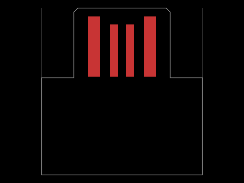 More from this authorpixalynx/edge-connectorConfigures USB-A, Micro-USB, and USB-C PCB-edge connectors with exposed copper contacts and automatically shaped, positioned board tongues.
 Similar packagegokul/usb-hub-boardA 4-layer 100×66 mm USB 2.0 hub board with a USB‑C upstream port, four protected downstream USB‑C/USB‑A ports, an integrated SD card reader, USB hub controllers, 3.3 V regulation, ESD protection, current-limited power switches, crystal oscillators, and filtering/passive components.
 Discover something newolivergrabinski/weather-stationA compact ESP32-S3 Wi‑Fi/Bluetooth module is powered by an AP2112K 3.3 V regulator, with a JST SH connector and blue status LED.