pixalynx/cm5-minimal-carrier
A 4-layer Raspberry Pi CM5 carrier board routes USB‑C 5V power through an RT9742 load switch with TVS protection and capacitive filtering, while providing ESD-protected HDMI output, CM5 connectors, test points, and ground/power planes.
- Version
- 0.1.1
- License
- unset
- Stars
- 0
docs/fabrication-checklist.md
# Fabrication-readiness checklist

**Release state: HOLD — engineering prototype, not approved for ordering.** No PCB or assembly order has been placed. Review exports exist to make the remaining checks concrete.

## Completed by the reproducible design build

- [x] 200 pin names checked against CM5 datasheet Release 3, Table 4.
- [x] Two correct physical 100-pin sockets; local-to-global pin numbering exported.
- [x] Exact official pad geometry, polarity/orientation, 34 mm socket centres, module outline and four Ø2.7 mm mounting holes.
- [x] All module grounds and six main power contacts connected; GPIO_VREF tied to module 3.3 V.
- [x] CC1/CC2 connected separately to CM5's PD controller; USB data/SBU left NC; no duplicate Rd.
- [x] No external supply driven onto the module's 3.3 V or 1.8 V outputs.
- [x] HDMI0 mapping, polarity, clock, DDC, CEC, HPD and protected +5 V checked.
- [x] ESD NC lands bridged in actual copper; no assumed internal feed-through.
- [x] All four HDMI pairs routed on top, no signal vias, lengths matched within 0.15 mm.
- [x] Separate L2 GND and L3 5 V planes; no signal traces on either inner plane.
- [x] Filled L2 ground is one connected region and covers all 6,954 HDMI trace-centre/edge samples.
- [x] Every intended emitted source connection checked; tsCircuit build/typecheck complete.
- [x] Independent KiCad fill/DRC: no excluded violations, zero shorts/clearance violations and zero unrouted items.
- [x] BOM/LCSC component identities and all schematic sheets exported.

Check `output/validation.json` after any edit: this list describes the delivered build, not future revisions.

## Revision B manufacturing preparation completed

- [x] Compared 12 HDMI signal mappings, direct CC wiring and six main-power contacts with the pinned CM5 MINIMA reference.
- [x] Obtained JLC calculator geometry for the specified four-layer stack: 0.1234 mm width / 0.2301 mm gap.
- [x] Corrected Gerber/drill/CPL origin to board bottom-left and audited the actual CAM coordinates.
- [x] Added six labelled bottom probe pads; excluded their paste, CAD bodies, BOM and placement entries.
- [x] Added top/bottom assembly drawings, pad-1 coordinates, IPC-D-356 electrical-test netlist and checksummed review bundle.
- [x] Verified 114 tented through-vias, eight plated slots, six NPTH holes and 0.14 mm minimum nominal mask web.

These checks do not replace the approvals below. See `output/manufacturing-audit.json` for the exact reviewed file hashes.

## Required before a prototype fabrication order

- [ ] Confirm **JLC04161H-3313**, 1.6 mm nominal, 1 oz outer / 0.5 oz inner copper, with JLCPCB.
- [ ] Approve 100 Ω differential controlled impedance/coupon; update 0.1234 mm / 0.2301 mm calculator geometry if required.
- [ ] Review complete high-speed fanouts and the CM5/connector/ESD channel with a suitable SI tool or hardware engineer.
- [ ] Re-run the complete build and inspect CAM layers after any change. Do not waive shorts or erase errors.
- [ ] Obtain connector current derating guidance for six main-power contacts and establish the intended load/temperature envelope.
- [ ] Review direct-VBUS bulk capacitance/inrush versus the intended USB-C/PD source and compliance requirement; revise the input switch architecture if necessary.
- [ ] Confirm LCSC identities, JLC Basic/Extended status, availability and any required global sourcing.
- [ ] Review the JLC placement preview for **every** reference, especially J1/J2, J3/J4 and U1–U4. CPL rotations/centroids are starting data, not pre-approved library rotations.
- [ ] Confirm bottom-side assembly for C2/C3/C6 and the mixed SMT/through-hole shield solder process.
- [ ] Approve manufacturer CAM/stencil treatment around 0.4 mm pitch sockets and slotted connector stakes; the exported via tenting and nominal mask webs are now audited.
- [ ] Confirm JLC’s supplied panel/tooling/fiducial arrangement for two-sided assembly; its current FAQ says it can add fiducials. Finished-board outline remains unchanged.
- [ ] Check actual CM5, cooler, 1.5 mm connector stack, screw supports, cable plug bodies and enclosure clearances using manufacturer mechanical models or samples.
- [ ] Use non-wireless, already programmed eMMC CM5. Confirm the image boots and enables HDMI0 on the programming carrier.
- [ ] Independent hardware review of schematic, connector drawings, netlist, stack-up and manufacturing files.

## Prototype bring-up and release testing

- [ ] Without CM5, inspect soldering and measure 5 V-to-GND resistance. A current-limited laboratory setup requires proper Type-C source behaviour or a documented test adapter.
- [ ] Capture successful 5 V / 5 A PD negotiation with the intended 5 A cable; verify both USB-C orientations.
- [ ] Measure inrush and monotonic startup at CM5 contacts. Verify 4.75–5.25 V over attach, boot and load steps.
- [ ] Check source current limiting and the HDMI switch's overload/reverse-current behaviour without damaging the module.
- [ ] Boot the pre-programmed module; verify storage and repeat cold power cycles.
- [ ] Reproduce the MINIMA issue #2 scenarios: HDMI attached during shutdown/restart, independently powered display, different qualified cables/supplies; measure rail decay/back-power at TP3/TP6.
- [ ] Test HDMI0 initially at 1080p60, then the intended final resolution/rate; verify EDID/DDC, HPD, CEC and representative monitors/cables.
- [ ] Measure connector/via/PCB temperatures and rail drop at worst intended sustained and peak current.
- [ ] Verify passive cooling and absence of thermal throttling at the intended ambient/workload.
- [ ] Run the required ESD/hot-plug tests and assess signal integrity. Passing software/DRC checks is not equivalent to these measurements.
- [ ] Record the qualified PSU, cable, CM5 SKU/firmware, display modes and enclosure in a release record.
Related Packages
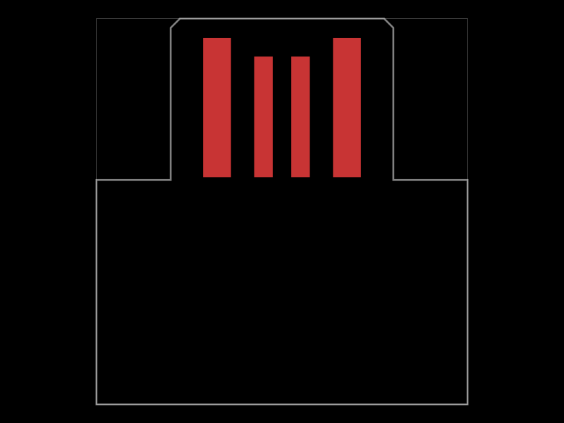 More from this authorpixalynx/edge-connectorConfigures USB-A, Micro-USB, and USB-C PCB-edge connectors with exposed copper contacts and automatically shaped, positioned board tongues.
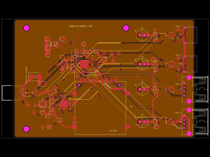 Similar packagegokul/usb-hub-boardA 4-layer 100×66 mm USB 2.0 hub board with a USB‑C upstream port, four protected downstream USB‑C/USB‑A ports, an integrated SD card reader, USB hub controllers, 3.3 V regulation, ESD protection, current-limited power switches, crystal oscillators, and filtering/passive components.
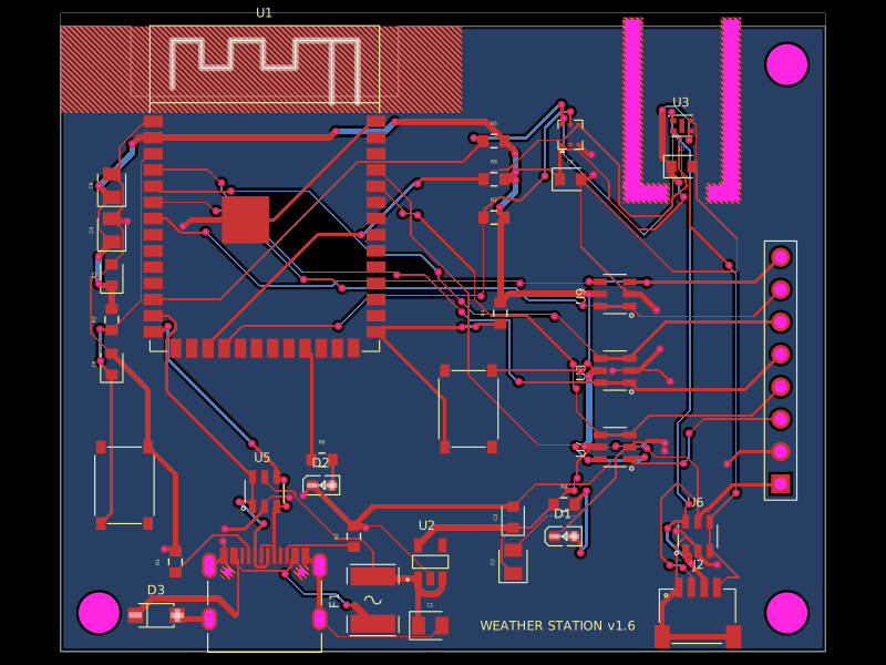 Discover something newolivergrabinski/weather-stationA compact ESP32-S3 Wi‑Fi/Bluetooth module is powered by an AP2112K 3.3 V regulator, with a JST SH connector and blue status LED.