muse/book-reading-clip-lamp
A Wi‑Fi/USB‑C ESP32‑S3 reading lamp with OV5640 camera, microphone, speaker amplifier, rechargeable Li‑Po power management, six-LED boost light, USB protection/charging detection, and a clip/gooseneck enclosure with external FlexPIFA antenna.
- Version
- 0.4.3
- License
- unset
- Stars
- 0
plug-in-assembly.txt
PLUG-IN FINAL ASSEMBLY REQUIREMENT — 08 October 2026

User requirement: no or minimal hand soldering; removable connectors for all
serviceable subassemblies. This replaces instructions to solder loose switch,
speaker, thermistor or battery leads during final product assembly.

Baseline architecture: one factory-assembled head PCB and a supplier-made
branched harness. A connector PCB in the base is an optional alternative;
connector family selection and base packaging depend on that decision.
Neither architecture removes the need for supplier-assembled switch/speaker
pigtails. Bare solder-lug parts are not complete assembly-ready purchases.

ALREADY PRESENT ON THE HEAD
J3: JST B8B-XH-A(LF)(SN) header, XHP-8 cable housing. Order the header fitted
by the PCB assembly service and order the cable with the matching contacts.
J2: FPC camera connector. Its existing camera-tail mating hold still applies.
U1: MHF1/U.FL antenna connection.
USB-C: soldered by the PCB assembly service; external plug-in charging cable.
Head light button, microphone and LEDs: factory-populated on the head PCB.

REQUIRED BASE SUBASSEMBLIES
BAT1 + NTC1: protected 1S 3.7 V / 4.2 V pack, factory-attached temperature
sensor and a polarized cable connector. Prefer a four-circuit battery/sensor
interface, preserving separate NTC return wiring. Do not solder to cell tabs.
SPK1: speaker supplied with attached pigtail and a keyed two-circuit connector.
SW1: existing PV5S24011G switch mechanism, supplied as a factory-wired switch
assembly with an insulated pigtail and removable connector.
SW3: existing 100SP1T1B1M1REH switch mechanism, supplied as a factory-wired
assembly with an insulated pigtail and removable connector. Only common 2 and
OFF lug 1 are used; unused lug 3 is insulated at the supplier.
HARNESS1: factory-crimped head plug, labeled removable base branches and a
factory-insulated ground distribution joint. No loose solder joints or bare
wire twisting during final assembly. Specify distinct keying/families/circuit
counts so the battery cannot mate with speaker, NTC or switch branches.

ELECTRICAL INTERFACE — preserve existing head pinout
J3.1: protected battery positive.
J3.2: battery negative plus switch common ground distribution.
J3.3: temperature sensor sense.
J3.4: temperature sensor dedicated return (ground at the head).
J3.5: speaker positive.
J3.6: speaker negative; electrically separate from ground.
J3.7: Chat input; momentary switch closes to J3.2.
J3.8: power-control input; OFF switch closes to J3.2, ON leaves open.

SOURCING
E-Switch explicitly offers wire leads, connectors and ready-to-use assemblies:
https://www.e-switch.com/support/get-wired-with-e-switch/
https://www.e-switch.com/news-events/blog/switches-simplified/all-panel-mount-switches-now-available-with-wire-leads/
These are custom assembly services, not a claim that either bare switch SKU
ships with a connector. Obtain an assembly drawing, price and minimum quantity.

Molex provides pre-crimped leads for several connector families:
https://www.molex.com/content/dam/molex/molex-dot-com/en_us/pdf/datasheets/987651-2631.pdf
Pre-crimped leads can avoid owning a crimp tool. Loose connector housings alone
do not meet this assembly requirement. Contacts, mating halves and wire gauges
must be specified together; connector current rating must match the harness.

NECK ASSEMBLY
The assembled XHP-8 plug does not pass through the current 4 mm neck bore.
Have the harness supplier thread the wires through the neck before inserting
contacts into the housings, and deliver the neck/harness as one subassembly.
Alternatively use pre-crimped contacts only after confirming each terminal and
its protective sleeve passes the bore; do not pull assembled plugs through it.

STATUS
This is the current assembly requirement and procurement specification. No
extra PCB, connector model or base cavity change is claimed by this document.
The present 3D model still shows bare switch terminals/direct base wiring.
Connector part numbers, strain relief, service access and enclosure clearances
must be completed after choosing harness-only or an assembled base connector
board. No supplier has been contacted and no components have been ordered.
Related Packages
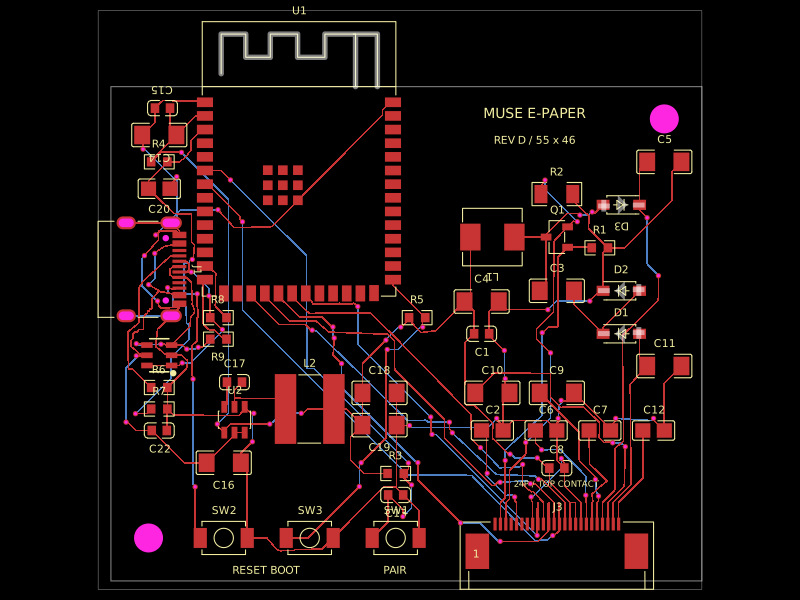 More from this authormuse/esp32-eink-displayA 55×46 mm two-layer ESP32-S3 e-paper controller board with USB‑C power/programming, buck regulation, FPC display connector, UC8179-style boost/charge-pump circuitry, ESD protection, controls, and routed passive components.
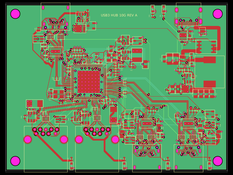 Similar packagepixalynx/usb3-hub-10gA USB 3.2 Gen 2 six-port hub board with USB-C PD power input, regulated 5 V/3.3 V/1.15 V rails, one upstream and four protected downstream USB-A/USB-C ports, SuperSpeed muxes, ESD protection, and controlled port power.
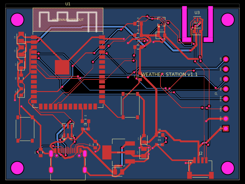 Discover something newolivergrabinski/tscircuit-weatherA 60×44 mm ESP32-S3 Wi‑Fi/BLE weather-station PCB with USB‑C power, 3.3 V regulation and ESD protection, temperature/humidity and UV/light sensors, status LEDs, buttons, Qwiic I²C expansion, debug GPIO header, and a printable enclosure.