mohan-bee/mini-mp3-player
Portable, battery-powered MP3 player hardware with USB charging, microSD storage, an MCU, VS10xx audio decoder, headphone output, status controls, and regulated power rails.
- Version
- 1.2.0
- License
- unset
- Stars
- 0
firmware/vendor/wch/Peripheral/src/ch32v20x_gpio.c
/********************************** (C) COPYRIGHT *******************************
* File Name : ch32v20x_gpio.c
* Author : WCH
* Version : V1.0.1
* Date : 2025/06/18
* Description : This file provides all the GPIO firmware functions.
*********************************************************************************
* Copyright (c) 2021 Nanjing Qinheng Microelectronics Co., Ltd.
* Attention: This software (modified or not) and binary are used for
* microcontroller manufactured by Nanjing Qinheng Microelectronics.
*******************************************************************************/
#include "ch32v20x_gpio.h"
#include "ch32v20x_rcc.h"
/* MASK */
#define ECR_PORTPINCONFIG_MASK ((uint16_t)0xFF80)
#define LSB_MASK ((uint16_t)0xFFFF)
#define DBGAFR_POSITION_MASK ((uint32_t)0x000F0000)
#define DBGAFR_SWJCFG_MASK ((uint32_t)0xF0FFFFFF)
#define DBGAFR_LOCATION_MASK ((uint32_t)0x00200000)
#define DBGAFR_NUMBITS_MASK ((uint32_t)0x00100000)
#if defined (CH32V20x_D6)
uint8_t MCU_Version = 0;
#endif
/*********************************************************************
* @fn GPIO_DeInit
*
* @brief Deinitializes the GPIOx peripheral registers to their default
* reset values.
*
* @param GPIOx - where x can be (A..D) to select the GPIO peripheral.
*
* @return none
*/
void GPIO_DeInit(GPIO_TypeDef *GPIOx)
{
if(GPIOx == GPIOA)
{
RCC_APB2PeriphResetCmd(RCC_APB2Periph_GPIOA, ENABLE);
RCC_APB2PeriphResetCmd(RCC_APB2Periph_GPIOA, DISABLE);
}
else if(GPIOx == GPIOB)
{
RCC_APB2PeriphResetCmd(RCC_APB2Periph_GPIOB, ENABLE);
RCC_APB2PeriphResetCmd(RCC_APB2Periph_GPIOB, DISABLE);
}
else if(GPIOx == GPIOC)
{
RCC_APB2PeriphResetCmd(RCC_APB2Periph_GPIOC, ENABLE);
RCC_APB2PeriphResetCmd(RCC_APB2Periph_GPIOC, DISABLE);
}
else if(GPIOx == GPIOD)
{
RCC_APB2PeriphResetCmd(RCC_APB2Periph_GPIOD, ENABLE);
RCC_APB2PeriphResetCmd(RCC_APB2Periph_GPIOD, DISABLE);
}
}
/*********************************************************************
* @fn GPIO_AFIODeInit
*
* @brief Deinitializes the Alternate Functions (remap, event control
* and EXTI configuration) registers to their default reset values.
*
* @return none
*/
void GPIO_AFIODeInit(void)
{
RCC_APB2PeriphResetCmd(RCC_APB2Periph_AFIO, ENABLE);
RCC_APB2PeriphResetCmd(RCC_APB2Periph_AFIO, DISABLE);
}
/*********************************************************************
* @fn GPIO_Init
*
* @brief GPIOx - where x can be (A..D) to select the GPIO peripheral.
*
* @param GPIO_InitStruct - pointer to a GPIO_InitTypeDef structure that
* contains the configuration information for the specified GPIO peripheral.
*
* @return none
*/
void GPIO_Init(GPIO_TypeDef *GPIOx, GPIO_InitTypeDef *GPIO_InitStruct)
{
uint32_t currentmode = 0x00, currentpin = 0x00, pinpos = 0x00, pos = 0x00;
uint32_t tmpreg = 0x00, pinmask = 0x00;
currentmode = ((uint32_t)GPIO_InitStruct->GPIO_Mode) & ((uint32_t)0x0F);
if((((uint32_t)GPIO_InitStruct->GPIO_Mode) & ((uint32_t)0x10)) != 0x00)
{
currentmode |= (uint32_t)GPIO_InitStruct->GPIO_Speed;
}
#if defined (CH32V20x_D6)
if(((*(uint32_t *) 0x40022030) & 0x0F000000) == 0)
{
MCU_Version = 1;
}
if((GPIOx == GPIOC) && MCU_Version){
GPIO_InitStruct->GPIO_Pin = GPIO_InitStruct->GPIO_Pin >> 13;
}
#endif
if(((uint32_t)GPIO_InitStruct->GPIO_Pin & ((uint32_t)0x00FF)) != 0x00)
{
tmpreg = GPIOx->CFGLR;
for(pinpos = 0x00; pinpos < 0x08; pinpos++)
{
pos = ((uint32_t)0x01) << pinpos;
currentpin = (GPIO_InitStruct->GPIO_Pin) & pos;
if(currentpin == pos)
{
pos = pinpos << 2;
pinmask = ((uint32_t)0x0F) << pos;
tmpreg &= ~pinmask;
tmpreg |= (currentmode << pos);
if(GPIO_InitStruct->GPIO_Mode == GPIO_Mode_IPD)
{
GPIOx->BCR = (((uint32_t)0x01) << pinpos);
}
else
{
if(GPIO_InitStruct->GPIO_Mode == GPIO_Mode_IPU)
{
GPIOx->BSHR = (((uint32_t)0x01) << pinpos);
}
}
}
}
GPIOx->CFGLR = tmpreg;
}
if(GPIO_InitStruct->GPIO_Pin > 0x00FF)
{
tmpreg = GPIOx->CFGHR;
for(pinpos = 0x00; pinpos < 0x08; pinpos++)
{
pos = (((uint32_t)0x01) << (pinpos + 0x08));
currentpin = ((GPIO_InitStruct->GPIO_Pin) & pos);
if(currentpin == pos)
{
pos = pinpos << 2;
pinmask = ((uint32_t)0x0F) << pos;
tmpreg &= ~pinmask;
tmpreg |= (currentmode << pos);
if(GPIO_InitStruct->GPIO_Mode == GPIO_Mode_IPD)
{
GPIOx->BCR = (((uint32_t)0x01) << (pinpos + 0x08));
}
if(GPIO_InitStruct->GPIO_Mode == GPIO_Mode_IPU)
{
GPIOx->BSHR = (((uint32_t)0x01) << (pinpos + 0x08));
}
}
}
GPIOx->CFGHR = tmpreg;
}
}
/*********************************************************************
* @fn GPIO_StructInit
*
* @brief Fills each GPIO_InitStruct member with its default
*
* @param GPIO_InitStruct - pointer to a GPIO_InitTypeDef structure
* which will be initialized.
*
* @return none
*/
void GPIO_StructInit(GPIO_InitTypeDef *GPIO_InitStruct)
{
GPIO_InitStruct->GPIO_Pin = GPIO_Pin_All;
GPIO_InitStruct->GPIO_Speed = GPIO_Speed_2MHz;
GPIO_InitStruct->GPIO_Mode = GPIO_Mode_IN_FLOATING;
}
/*********************************************************************
* @fn GPIO_ReadInputDataBit
*
* @brief GPIOx - where x can be (A..D) to select the GPIO peripheral.
*
* @param GPIO_Pin - specifies the port bit to read.
* This parameter can be GPIO_Pin_x where x can be (0..15).
*
* @return The input port pin value.
*/
uint8_t GPIO_ReadInputDataBit(GPIO_TypeDef *GPIOx, uint16_t GPIO_Pin)
{
uint8_t bitstatus = 0x00;
#if defined (CH32V20x_D6)
if((GPIOx == GPIOC) && MCU_Version){
GPIO_Pin = GPIO_Pin >> 13;
}
#endif
if((GPIOx->INDR & GPIO_Pin) != (uint32_t)Bit_RESET)
{
bitstatus = (uint8_t)Bit_SET;
}
else
{
bitstatus = (uint8_t)Bit_RESET;
}
return bitstatus;
}
/*********************************************************************
* @fn GPIO_ReadInputData
*
* @brief Reads the specified GPIO input data port.
*
* @param GPIOx - where x can be (A..D) to select the GPIO peripheral.
*
* @return The output port pin value.
*/
uint16_t GPIO_ReadInputData(GPIO_TypeDef *GPIOx)
{
uint16_t val;
#if defined (CH32V20x_D6)
if((GPIOx == GPIOC) && MCU_Version){
val = ( uint16_t )(GPIOx->INDR << 13);
}
else{
val = ( uint16_t )GPIOx->INDR;
}
#else
val = ( uint16_t )GPIOx->INDR;
#endif
return ( val );
}
/*********************************************************************
* @fn GPIO_ReadOutputDataBit
*
* @brief Reads the specified output data port bit.
*
* @param GPIOx - where x can be (A..D) to select the GPIO peripheral.
* GPIO_Pin - specifies the port bit to read.
* This parameter can be GPIO_Pin_x where x can be (0..15).
*
* @return none
*/
uint8_t GPIO_ReadOutputDataBit(GPIO_TypeDef *GPIOx, uint16_t GPIO_Pin)
{
uint8_t bitstatus = 0x00;
#if defined (CH32V20x_D6)
if((GPIOx == GPIOC) && MCU_Version){
GPIO_Pin = GPIO_Pin >> 13;
}
#endif
if((GPIOx->OUTDR & GPIO_Pin) != (uint32_t)Bit_RESET)
{
bitstatus = (uint8_t)Bit_SET;
}
else
{
bitstatus = (uint8_t)Bit_RESET;
}
return bitstatus;
}
/*********************************************************************
* @fn GPIO_ReadOutputData
*
* @brief Reads the specified GPIO output data port.
*
* @param GPIOx - where x can be (A..D) to select the GPIO peripheral.
*
* @return GPIO output port pin value.
*/
uint16_t GPIO_ReadOutputData(GPIO_TypeDef *GPIOx)
{
uint16_t val;
#if defined (CH32V20x_D6)
if((GPIOx == GPIOC) && MCU_Version){
val = ( uint16_t )(GPIOx->OUTDR << 13);
}
else{
val = ( uint16_t )GPIOx->OUTDR;
}
#else
val = ( uint16_t )GPIOx->OUTDR;
#endif
return ( val );
}
/*********************************************************************
* @fn GPIO_SetBits
*
* @brief Sets the selected data port bits.
*
* @param GPIOx - where x can be (A..D) to select the GPIO peripheral.
* GPIO_Pin - specifies the port bits to be written.
* This parameter can be any combination of GPIO_Pin_x where x can be (0..15).
*
* @return none
*/
void GPIO_SetBits(GPIO_TypeDef *GPIOx, uint16_t GPIO_Pin)
{
#if defined (CH32V20x_D6)
if((GPIOx == GPIOC) && MCU_Version){
GPIO_Pin = GPIO_Pin >> 13;
}
#endif
GPIOx->BSHR = GPIO_Pin;
}
/*********************************************************************
* @fn GPIO_ResetBits
*
* @brief Clears the selected data port bits.
*
* @param GPIOx - where x can be (A..D) to select the GPIO peripheral.
* GPIO_Pin - specifies the port bits to be written.
* This parameter can be any combination of GPIO_Pin_x where x can be (0..15).
*
* @return none
*/
void GPIO_ResetBits(GPIO_TypeDef *GPIOx, uint16_t GPIO_Pin)
{
#if defined (CH32V20x_D6)
if((GPIOx == GPIOC) && MCU_Version){
GPIO_Pin = GPIO_Pin >> 13;
}
#endif
GPIOx->BCR = GPIO_Pin;
}
/*********************************************************************
* @fn GPIO_WriteBit
*
* @brief Sets or clears the selected data port bit.
*
* @param GPIO_Pin - specifies the port bit to be written.
* This parameter can be one of GPIO_Pin_x where x can be (0..15).
* BitVal - specifies the value to be written to the selected bit.
* Bit_RESET - to clear the port pin.
* Bit_SET - to set the port pin.
*
* @return none
*/
void GPIO_WriteBit(GPIO_TypeDef *GPIOx, uint16_t GPIO_Pin, BitAction BitVal)
{
#if defined (CH32V20x_D6)
if((GPIOx == GPIOC) && MCU_Version){
GPIO_Pin = GPIO_Pin >> 13;
}
#endif
if(BitVal != Bit_RESET)
{
GPIOx->BSHR = GPIO_Pin;
}
else
{
GPIOx->BCR = GPIO_Pin;
}
}
/*********************************************************************
* @fn GPIO_Write
*
* @brief Writes data to the specified GPIO data port.
*
* @param GPIOx - where x can be (A..D) to select the GPIO peripheral.
* PortVal - specifies the value to be written to the port output data register.
*
* @return none
*/
void GPIO_Write(GPIO_TypeDef *GPIOx, uint16_t PortVal)
{
#if defined (CH32V20x_D6)
if((GPIOx == GPIOC) && MCU_Version){
PortVal = PortVal >> 13;
}
#endif
GPIOx->OUTDR = PortVal;
}
/*********************************************************************
* @fn GPIO_PinLockConfig
*
* @brief Locks GPIO Pins configuration registers.
*
* @param GPIOx - where x can be (A..D) to select the GPIO peripheral.
* GPIO_Pin - specifies the port bit to be written.
* This parameter can be any combination of GPIO_Pin_x where x can be (0..15).
*
* @return none
*/
void GPIO_PinLockConfig(GPIO_TypeDef *GPIOx, uint16_t GPIO_Pin)
{
uint32_t tmp = 0x00010000;
#if defined (CH32V20x_D6)
if((GPIOx == GPIOC) && MCU_Version){
GPIO_Pin = GPIO_Pin >> 13;
}
#endif
tmp |= GPIO_Pin;
GPIOx->LCKR = tmp;
GPIOx->LCKR = GPIO_Pin;
GPIOx->LCKR = tmp;
tmp = GPIOx->LCKR;
tmp = GPIOx->LCKR;
}
/*********************************************************************
* @fn GPIO_EventOutputConfig
*
* @brief Selects the GPIO pin used as Event output.
*
* @param GPIO_PortSource - selects the GPIO port to be used as source
* for Event output.
* This parameter can be GPIO_PortSourceGPIOx where x can be (A..D).
* GPIO_PinSource - specifies the pin for the Event output.
* This parameter can be GPIO_PinSourcex where x can be (0..15).
*
* @return none
*/
void GPIO_EventOutputConfig(uint8_t GPIO_PortSource, uint8_t GPIO_PinSource)
{
uint32_t tmpreg = 0x00;
tmpreg = AFIO->ECR;
tmpreg &= ECR_PORTPINCONFIG_MASK;
tmpreg |= (uint32_t)GPIO_PortSource << 0x04;
tmpreg |= GPIO_PinSource;
AFIO->ECR = tmpreg;
}
/*********************************************************************
* @fn GPIO_EventOutputCmd
*
* @brief Enables or disables the Event Output.
*
* @param NewState - ENABLE or DISABLE.
*
* @return none
*/
void GPIO_EventOutputCmd(FunctionalState NewState)
{
if(NewState)
{
AFIO->ECR |= (1 << 7);
}
else
{
AFIO->ECR &= ~(1 << 7);
}
}
/*********************************************************************
* @fn GPIO_PinRemapConfig
*
* @brief Changes the mapping of the specified pin.
*
* @param GPIO_Remap - selects the pin to remap.
* GPIO_Remap_SPI1 - SPI1 Alternate Function mapping
* GPIO_Remap_I2C1 - I2C1 Alternate Function mapping
* GPIO_Remap_USART1 - USART1 Alternate Function mapping
* GPIO_Remap_USART2 - USART2 Alternate Function mapping
* GPIO_PartialRemap_USART3 - USART3 Partial Alternate Function mapping
* GPIO_FullRemap_USART3 - USART3 Full Alternate Function mapping
* GPIO_PartialRemap_TIM1 - TIM1 Partial Alternate Function mapping
* GPIO_FullRemap_TIM1 - TIM1 Full Alternate Function mapping
* GPIO_PartialRemap1_TIM2 - TIM2 Partial1 Alternate Function mapping
* GPIO_PartialRemap2_TIM2 - TIM2 Partial2 Alternate Function mapping
* GPIO_FullRemap_TIM2 - TIM2 Full Alternate Function mapping
* GPIO_PartialRemap_TIM3 - TIM3 Partial Alternate Function mapping
* GPIO_FullRemap_TIM3 - TIM3 Full Alternate Function mapping
* GPIO_Remap_TIM4 - TIM4 Alternate Function mapping
* GPIO_Remap1_CAN1 - CAN1 Alternate Function mapping
* GPIO_Remap2_CAN1 - CAN1 Alternate Function mapping
* GPIO_Remap_PD0PD1 - PD0 and PD1 Alternate Function mapping
* GPIO_Remap_ADC1_ETRGINJ - ADC1 External Trigger Injected Conversion remapping
* GPIO_Remap_ADC1_ETRGREG - ADC1 External Trigger Regular Conversion remapping
* GPIO_Remap_ADC2_ETRGINJ - ADC2 External Trigger Injected Conversion remapping
* GPIO_Remap_ADC2_ETRGREG - ADC2 External Trigger Regular Conversion remapping
* GPIO_Remap_ETH - Ethernet remapping
* GPIO_Remap_MII_RMII_SEL - MII or RMII selection
* GPIO_Remap_SWJ_Disable - Full SWJ Disabled
* GPIO_Remap_TIM2ITR1_PTP_SOF - Ethernet PTP output or USB OTG SOF (Start of Frame) connected
* to TIM2 Internal Trigger 1 for calibration
* GPIO_Remap_TIM2ITR1_PTP_SOF - Ethernet PTP output or USB OTG SOF (Start of Frame)
* GPIO_Remap_FSMC_NADV - FSMC_NADV Alternate Function mapping
* GPIO_PartialRemap_USART4 - USART4 Partial Alternate Function mapping
* GPIO_FullRemap_USART4 - USART4 Full Alternate Function mapping
* GPIO_Remap_USART1_HighBit - USART1 Alternate Function mapping high bit
* NewState - ENABLE or DISABLE.
*
* @return none
*/
void GPIO_PinRemapConfig(uint32_t GPIO_Remap, FunctionalState NewState)
{
uint32_t tmp = 0x00, tmp1 = 0x00, tmpreg = 0x00, tmpmask = 0x00;
if((GPIO_Remap & 0x80000000) == 0x80000000)
{
tmpreg = AFIO->PCFR2;
}
else
{
tmpreg = AFIO->PCFR1;
if(((*(uint32_t *) 0x40022030) & 0x0F000000) == 0){
tmpreg = ((tmpreg>>1)&0xFFFFE000)|(tmpreg&0x00001FFF);
}
}
tmpmask = (GPIO_Remap & DBGAFR_POSITION_MASK) >> 0x10;
tmp = GPIO_Remap & LSB_MASK;
/* Clear bit */
if((GPIO_Remap & 0x80000000) == 0x80000000)
{ /* PCFR2 */
if((GPIO_Remap & (DBGAFR_LOCATION_MASK | DBGAFR_NUMBITS_MASK)) == (DBGAFR_LOCATION_MASK | DBGAFR_NUMBITS_MASK)) /* [31:16] 2bit */
{
tmp1 = ((uint32_t)0x03) << (tmpmask + 0x10);
tmpreg &= ~tmp1;
}
else if((GPIO_Remap & DBGAFR_NUMBITS_MASK) == DBGAFR_NUMBITS_MASK) /* [15:0] 2bit */
{
tmp1 = ((uint32_t)0x03) << tmpmask;
tmpreg &= ~tmp1;
}
else /* [31:0] 1bit */
{
tmpreg &= ~(tmp << (((GPIO_Remap & 0x7FFFFFFF ) >> 0x15) * 0x10));
}
}
else
{ /* PCFR1 */
if((GPIO_Remap & (DBGAFR_LOCATION_MASK | DBGAFR_NUMBITS_MASK)) == (DBGAFR_LOCATION_MASK | DBGAFR_NUMBITS_MASK)) /* [26:24] 3bit SWD_JTAG */
{
tmpreg &= DBGAFR_SWJCFG_MASK;
AFIO->PCFR1 &= DBGAFR_SWJCFG_MASK;
}
else if((GPIO_Remap & DBGAFR_NUMBITS_MASK) == DBGAFR_NUMBITS_MASK) /* [15:0] 2bit */
{
tmp1 = ((uint32_t)0x03) << tmpmask;
tmpreg &= ~tmp1;
tmpreg |= ~DBGAFR_SWJCFG_MASK;
}
else /* [31:0] 1bit */
{
tmpreg &= ~(tmp << ((GPIO_Remap >> 0x15) * 0x10));
tmpreg |= ~DBGAFR_SWJCFG_MASK;
}
}
/* Set bit */
if(NewState != DISABLE)
{
tmpreg |= (tmp << (((GPIO_Remap & 0x7FFFFFFF )>> 0x15) * 0x10));
}
if((GPIO_Remap & 0x80000000) == 0x80000000)
{
AFIO->PCFR2 = tmpreg;
}
else
{
AFIO->PCFR1 = tmpreg;
}
}
/*********************************************************************
* @fn GPIO_EXTILineConfig
*
* @brief Selects the GPIO pin used as EXTI Line.
*
* @param GPIO_PortSource - selects the GPIO port to be used as source for EXTI lines.
* This parameter can be GPIO_PortSourceGPIOx where x can be (A..D).
* GPIO_PinSource - specifies the EXTI line to be configured.
* This parameter can be GPIO_PinSourcex where x can be (0..15).
*
* @return none
*/
void GPIO_EXTILineConfig(uint8_t GPIO_PortSource, uint8_t GPIO_PinSource)
{
uint32_t tmp = 0x00;
tmp = ((uint32_t)0x0F) << (0x04 * (GPIO_PinSource & (uint8_t)0x03));
AFIO->EXTICR[GPIO_PinSource >> 0x02] &= ~tmp;
AFIO->EXTICR[GPIO_PinSource >> 0x02] |= (((uint32_t)GPIO_PortSource) << (0x04 * (GPIO_PinSource & (uint8_t)0x03)));
}
/*********************************************************************
* @fn GPIO_ETH_MediaInterfaceConfig
*
* @brief Selects the Ethernet media interface.
*
* @param GPIO_ETH_MediaInterface - specifies the Media Interface mode.
* GPIO_ETH_MediaInterface_MII - MII mode
* GPIO_ETH_MediaInterface_RMII - RMII mode
*
* @return none
*/
void GPIO_ETH_MediaInterfaceConfig(uint32_t GPIO_ETH_MediaInterface)
{
if(GPIO_ETH_MediaInterface)
{
AFIO->PCFR1 |= (1 << 23);
}
else
{
AFIO->PCFR1 &= ~(1 << 23);
}
}
/*********************************************************************
* @fn GPIO_IPD_Unused
*
* @brief Configure unused GPIO as input pull-up.
*
* @param none
*
* @return none
*/
void GPIO_IPD_Unused(void)
{
GPIO_InitTypeDef GPIO_InitStructure = {0};
uint32_t chip = 0;
RCC_APB2PeriphClockCmd(RCC_APB2Periph_GPIOA | RCC_APB2Periph_GPIOB \
| RCC_APB2Periph_GPIOC | RCC_APB2Periph_GPIOD|RCC_APB2Periph_AFIO,ENABLE);
chip = *( uint32_t * )0x1FFFF704 & (~0x000000F0);
switch(chip)
{
#ifdef CH32V20x_D6
case 0x20370500: //CH32V203F6P
{
GPIO_InitStructure.GPIO_Pin = GPIO_Pin_8|GPIO_Pin_9\
|GPIO_Pin_10|GPIO_Pin_15;
GPIO_InitStructure.GPIO_Mode = GPIO_Mode_IPU;
GPIO_Init(GPIOA, &GPIO_InitStructure);
GPIO_InitStructure.GPIO_Pin = GPIO_Pin_0\
|GPIO_Pin_3|GPIO_Pin_4\
|GPIO_Pin_5|GPIO_Pin_6\
|GPIO_Pin_7|GPIO_Pin_9\
|GPIO_Pin_10|GPIO_Pin_11\
|GPIO_Pin_12|GPIO_Pin_13\
|GPIO_Pin_14|GPIO_Pin_15;
GPIO_InitStructure.GPIO_Mode = GPIO_Mode_IPU;
GPIO_Init(GPIOB, &GPIO_InitStructure);
GPIO_InitStructure.GPIO_Pin = GPIO_Pin_0|GPIO_Pin_1\
|GPIO_Pin_2|GPIO_Pin_3\
|GPIO_Pin_4|GPIO_Pin_5\
|GPIO_Pin_6|GPIO_Pin_7\
|GPIO_Pin_8|GPIO_Pin_9\
|GPIO_Pin_10|GPIO_Pin_11\
|GPIO_Pin_12|GPIO_Pin_13\
|GPIO_Pin_14|GPIO_Pin_15;
GPIO_InitStructure.GPIO_Mode = GPIO_Mode_IPU;
GPIO_Init(GPIOC, &GPIO_InitStructure);
GPIO_InitStructure.GPIO_Pin = GPIO_Pin_2|GPIO_Pin_3\
|GPIO_Pin_4|GPIO_Pin_5\
|GPIO_Pin_6;
GPIO_InitStructure.GPIO_Mode = GPIO_Mode_IPU;
GPIO_Init(GPIOD, &GPIO_InitStructure);
break;
}
case 0x203A0500: //CH32V203F8P
{
GPIO_PinRemapConfig(GPIO_Remap_PD01, ENABLE);
GPIO_InitStructure.GPIO_Pin = GPIO_Pin_11|GPIO_Pin_12\
|GPIO_Pin_15;
GPIO_InitStructure.GPIO_Mode = GPIO_Mode_IPU;
GPIO_Init(GPIOA, &GPIO_InitStructure);
GPIO_InitStructure.GPIO_Pin = GPIO_Pin_2;
GPIO_InitStructure.GPIO_Mode = GPIO_Mode_IPD;
GPIO_Init(GPIOB, &GPIO_InitStructure);
GPIO_InitStructure.GPIO_Pin = GPIO_Pin_1\
|GPIO_Pin_3|GPIO_Pin_4\
|GPIO_Pin_5|GPIO_Pin_8\
|GPIO_Pin_9|GPIO_Pin_10\
|GPIO_Pin_11|GPIO_Pin_12;
GPIO_InitStructure.GPIO_Mode = GPIO_Mode_IPU;
GPIO_Init(GPIOB, &GPIO_InitStructure);
GPIO_InitStructure.GPIO_Pin = GPIO_Pin_0|GPIO_Pin_1\
|GPIO_Pin_2|GPIO_Pin_3\
|GPIO_Pin_4|GPIO_Pin_5\
|GPIO_Pin_6|GPIO_Pin_7\
|GPIO_Pin_8|GPIO_Pin_9\
|GPIO_Pin_10|GPIO_Pin_11\
|GPIO_Pin_12|GPIO_Pin_13\
|GPIO_Pin_14|GPIO_Pin_15;
GPIO_InitStructure.GPIO_Mode = GPIO_Mode_IPU;
GPIO_Init(GPIOC, &GPIO_InitStructure);
GPIO_InitStructure.GPIO_Pin = GPIO_Pin_0|GPIO_Pin_1|GPIO_Pin_2|GPIO_Pin_3\
|GPIO_Pin_4|GPIO_Pin_5\
|GPIO_Pin_6;
GPIO_InitStructure.GPIO_Mode = GPIO_Mode_IPU;
GPIO_Init(GPIOD, &GPIO_InitStructure);
break;
}
case 0x203D0500: //CH32V203F8U
{
GPIO_PinRemapConfig(GPIO_Remap_PD01, ENABLE);
GPIO_InitStructure.GPIO_Pin = GPIO_Pin_15;
GPIO_InitStructure.GPIO_Mode = GPIO_Mode_IPU;
GPIO_Init(GPIOA, &GPIO_InitStructure);
GPIO_InitStructure.GPIO_Pin = GPIO_Pin_2;
GPIO_InitStructure.GPIO_Mode = GPIO_Mode_IPD;
GPIO_Init(GPIOB, &GPIO_InitStructure);
GPIO_InitStructure.GPIO_Pin = GPIO_Pin_3\
|GPIO_Pin_4|GPIO_Pin_5\
|GPIO_Pin_6|GPIO_Pin_7\
|GPIO_Pin_8|GPIO_Pin_9\
|GPIO_Pin_12|GPIO_Pin_13;
GPIO_InitStructure.GPIO_Mode = GPIO_Mode_IPU;
GPIO_Init(GPIOB, &GPIO_InitStructure);
GPIO_InitStructure.GPIO_Pin = GPIO_Pin_0|GPIO_Pin_1\
|GPIO_Pin_2|GPIO_Pin_3\
|GPIO_Pin_4|GPIO_Pin_5\
|GPIO_Pin_6|GPIO_Pin_7\
|GPIO_Pin_8|GPIO_Pin_9\
|GPIO_Pin_10|GPIO_Pin_11\
|GPIO_Pin_12|GPIO_Pin_13\
|GPIO_Pin_14|GPIO_Pin_15;
GPIO_InitStructure.GPIO_Mode = GPIO_Mode_IPU;
GPIO_Init(GPIOC, &GPIO_InitStructure);
GPIO_InitStructure.GPIO_Pin = GPIO_Pin_0|GPIO_Pin_1|GPIO_Pin_2|GPIO_Pin_3\
|GPIO_Pin_4|GPIO_Pin_5\
|GPIO_Pin_6;
GPIO_InitStructure.GPIO_Mode = GPIO_Mode_IPU;
GPIO_Init(GPIOD, &GPIO_InitStructure);
break;
}
case 0x20360500: //CH32V203G6U
{
GPIO_InitStructure.GPIO_Pin = GPIO_Pin_8;
GPIO_InitStructure.GPIO_Mode = GPIO_Mode_IPU;
GPIO_Init(GPIOA, &GPIO_InitStructure);
GPIO_InitStructure.GPIO_Pin = GPIO_Pin_2;
GPIO_InitStructure.GPIO_Mode = GPIO_Mode_IPD;
GPIO_Init(GPIOB, &GPIO_InitStructure);
GPIO_InitStructure.GPIO_Pin = GPIO_Pin_9\
|GPIO_Pin_10|GPIO_Pin_11\
|GPIO_Pin_12|GPIO_Pin_13\
|GPIO_Pin_14|GPIO_Pin_15;
GPIO_InitStructure.GPIO_Mode = GPIO_Mode_IPU;
GPIO_Init(GPIOB, &GPIO_InitStructure);
GPIO_InitStructure.GPIO_Pin = GPIO_Pin_0|GPIO_Pin_1\
|GPIO_Pin_2|GPIO_Pin_3\
|GPIO_Pin_4|GPIO_Pin_5\
|GPIO_Pin_6|GPIO_Pin_7\
|GPIO_Pin_8|GPIO_Pin_9\
|GPIO_Pin_10|GPIO_Pin_11\
|GPIO_Pin_12|GPIO_Pin_13\
|GPIO_Pin_14|GPIO_Pin_15;
GPIO_InitStructure.GPIO_Mode = GPIO_Mode_IPU;
GPIO_Init(GPIOC, &GPIO_InitStructure);
GPIO_InitStructure.GPIO_Pin = GPIO_Pin_2|GPIO_Pin_3\
|GPIO_Pin_4|GPIO_Pin_5\
|GPIO_Pin_6;
GPIO_InitStructure.GPIO_Mode = GPIO_Mode_IPU;
GPIO_Init(GPIOD, &GPIO_InitStructure);
break;
}
case 0x203B0500: //CH32V203G8R
{
GPIO_PinRemapConfig(GPIO_Remap_PD01, ENABLE);
GPIO_InitStructure.GPIO_Pin = GPIO_Pin_15;
GPIO_InitStructure.GPIO_Mode = GPIO_Mode_IPU;
GPIO_Init(GPIOA, &GPIO_InitStructure);
GPIO_InitStructure.GPIO_Pin = GPIO_Pin_2;
GPIO_InitStructure.GPIO_Mode = GPIO_Mode_IPD;
GPIO_Init(GPIOB, &GPIO_InitStructure);
GPIO_InitStructure.GPIO_Pin = GPIO_Pin_3\
|GPIO_Pin_4|GPIO_Pin_9;
GPIO_InitStructure.GPIO_Mode = GPIO_Mode_IPU;
GPIO_Init(GPIOB, &GPIO_InitStructure);
GPIO_InitStructure.GPIO_Pin = GPIO_Pin_0|GPIO_Pin_1\
|GPIO_Pin_2|GPIO_Pin_3\
|GPIO_Pin_4|GPIO_Pin_5\
|GPIO_Pin_6|GPIO_Pin_7\
|GPIO_Pin_8|GPIO_Pin_9\
|GPIO_Pin_10|GPIO_Pin_11\
|GPIO_Pin_12|GPIO_Pin_13\
|GPIO_Pin_14|GPIO_Pin_15;
GPIO_InitStructure.GPIO_Mode = GPIO_Mode_IPU;
GPIO_Init(GPIOC, &GPIO_InitStructure);
GPIO_InitStructure.GPIO_Pin = GPIO_Pin_0|GPIO_Pin_1|GPIO_Pin_2|GPIO_Pin_3\
|GPIO_Pin_4|GPIO_Pin_5\
|GPIO_Pin_6;
GPIO_InitStructure.GPIO_Mode = GPIO_Mode_IPU;
GPIO_Init(GPIOD, &GPIO_InitStructure);
break;
}
case 0x20320500: //CH32V203K8T
{
GPIO_InitStructure.GPIO_Pin = GPIO_Pin_2;
GPIO_InitStructure.GPIO_Mode = GPIO_Mode_IPD;
GPIO_Init(GPIOB, &GPIO_InitStructure);
GPIO_InitStructure.GPIO_Pin = GPIO_Pin_9\
|GPIO_Pin_10|GPIO_Pin_11\
|GPIO_Pin_12|GPIO_Pin_13\
|GPIO_Pin_14|GPIO_Pin_15;
GPIO_InitStructure.GPIO_Mode = GPIO_Mode_IPU;
GPIO_Init(GPIOB, &GPIO_InitStructure);
GPIO_InitStructure.GPIO_Pin = GPIO_Pin_0|GPIO_Pin_1\
|GPIO_Pin_2|GPIO_Pin_3\
|GPIO_Pin_4|GPIO_Pin_5\
|GPIO_Pin_6|GPIO_Pin_7\
|GPIO_Pin_8|GPIO_Pin_9\
|GPIO_Pin_10|GPIO_Pin_11\
|GPIO_Pin_12|GPIO_Pin_13\
|GPIO_Pin_14|GPIO_Pin_15;
GPIO_InitStructure.GPIO_Mode = GPIO_Mode_IPU;
GPIO_Init(GPIOC, &GPIO_InitStructure);
GPIO_InitStructure.GPIO_Pin = GPIO_Pin_2|GPIO_Pin_3\
|GPIO_Pin_4|GPIO_Pin_5\
|GPIO_Pin_6;
GPIO_InitStructure.GPIO_Mode = GPIO_Mode_IPU;
GPIO_Init(GPIOD, &GPIO_InitStructure);
break;
}
case 0x20321500: //CH32V203K8U
{
GPIO_InitStructure.GPIO_Pin = GPIO_Pin_11\
|GPIO_Pin_12|GPIO_Pin_13\
|GPIO_Pin_14;
GPIO_InitStructure.GPIO_Mode = GPIO_Mode_IPU;
GPIO_Init(GPIOB, &GPIO_InitStructure);
GPIO_InitStructure.GPIO_Pin = GPIO_Pin_0|GPIO_Pin_1\
|GPIO_Pin_2|GPIO_Pin_3\
|GPIO_Pin_4|GPIO_Pin_5\
|GPIO_Pin_6|GPIO_Pin_7\
|GPIO_Pin_8|GPIO_Pin_9\
|GPIO_Pin_10|GPIO_Pin_11\
|GPIO_Pin_12|GPIO_Pin_13\
|GPIO_Pin_14|GPIO_Pin_15;
GPIO_InitStructure.GPIO_Mode = GPIO_Mode_IPU;
GPIO_Init(GPIOC, &GPIO_InitStructure);
GPIO_InitStructure.GPIO_Pin = GPIO_Pin_2|GPIO_Pin_3\
|GPIO_Pin_4|GPIO_Pin_5\
|GPIO_Pin_6;
GPIO_InitStructure.GPIO_Mode = GPIO_Mode_IPU;
GPIO_Init(GPIOD, &GPIO_InitStructure);
break;
}
case 0x20330500: //CH32V203C6T
{
GPIO_InitStructure.GPIO_Pin = GPIO_Pin_0|GPIO_Pin_1\
|GPIO_Pin_2|GPIO_Pin_3\
|GPIO_Pin_4|GPIO_Pin_5\
|GPIO_Pin_6|GPIO_Pin_7\
|GPIO_Pin_8|GPIO_Pin_9\
|GPIO_Pin_10|GPIO_Pin_11\
|GPIO_Pin_12;
GPIO_InitStructure.GPIO_Mode = GPIO_Mode_IPU;
GPIO_Init(GPIOC, &GPIO_InitStructure);
GPIO_InitStructure.GPIO_Pin = GPIO_Pin_2|GPIO_Pin_3\
|GPIO_Pin_4|GPIO_Pin_5\
|GPIO_Pin_6;
GPIO_InitStructure.GPIO_Mode = GPIO_Mode_IPU;
GPIO_Init(GPIOD, &GPIO_InitStructure);
break;
}
case 0x20310500: //CH32V203C8T
{
GPIO_InitStructure.GPIO_Pin = GPIO_Pin_0|GPIO_Pin_1\
|GPIO_Pin_2|GPIO_Pin_3\
|GPIO_Pin_4|GPIO_Pin_5\
|GPIO_Pin_6|GPIO_Pin_7\
|GPIO_Pin_8|GPIO_Pin_9\
|GPIO_Pin_10|GPIO_Pin_11\
|GPIO_Pin_12;
GPIO_InitStructure.GPIO_Mode = GPIO_Mode_IPU;
GPIO_Init(GPIOC, &GPIO_InitStructure);
GPIO_InitStructure.GPIO_Pin = GPIO_Pin_2|GPIO_Pin_3\
|GPIO_Pin_4|GPIO_Pin_5\
|GPIO_Pin_6;
GPIO_InitStructure.GPIO_Mode = GPIO_Mode_IPU;
GPIO_Init(GPIOD, &GPIO_InitStructure);
break;
}
case 0x20300500: //CH32V203C8U
{
GPIO_InitStructure.GPIO_Pin = GPIO_Pin_0|GPIO_Pin_1\
|GPIO_Pin_2|GPIO_Pin_3\
|GPIO_Pin_4|GPIO_Pin_5\
|GPIO_Pin_6|GPIO_Pin_7\
|GPIO_Pin_8|GPIO_Pin_9\
|GPIO_Pin_10|GPIO_Pin_11\
|GPIO_Pin_12;
GPIO_InitStructure.GPIO_Mode = GPIO_Mode_IPU;
GPIO_Init(GPIOC, &GPIO_InitStructure);
GPIO_InitStructure.GPIO_Pin = GPIO_Pin_2|GPIO_Pin_3\
|GPIO_Pin_4|GPIO_Pin_5\
|GPIO_Pin_6;
GPIO_InitStructure.GPIO_Mode = GPIO_Mode_IPU;
GPIO_Init(GPIOD, &GPIO_InitStructure);
break;
}
#elif defined(CH32V20x_D8)
case 0x2034050C: //CH32V203RBT
{
GPIO_InitStructure.GPIO_Pin = GPIO_Pin_3|GPIO_Pin_4\
|GPIO_Pin_5|GPIO_Pin_6;
GPIO_InitStructure.GPIO_Mode = GPIO_Mode_IPU;
GPIO_Init(GPIOD, &GPIO_InitStructure);
break;
}
#elif defined(CH32V20x_D8W)
case 0x2083050C: //CH32V208GBU
{
GPIO_InitStructure.GPIO_Pin = GPIO_Pin_8|GPIO_Pin_9\
|GPIO_Pin_10|GPIO_Pin_15;
GPIO_InitStructure.GPIO_Mode = GPIO_Mode_IPU;
GPIO_Init(GPIOA, &GPIO_InitStructure);
GPIO_InitStructure.GPIO_Pin = GPIO_Pin_2;
GPIO_InitStructure.GPIO_Mode = GPIO_Mode_IPD;
GPIO_Init(GPIOB, &GPIO_InitStructure);
GPIO_InitStructure.GPIO_Pin = GPIO_Pin_0|GPIO_Pin_1\
|GPIO_Pin_3\
|GPIO_Pin_4|GPIO_Pin_5\
|GPIO_Pin_9|GPIO_Pin_10\
|GPIO_Pin_11|GPIO_Pin_12\
|GPIO_Pin_13|GPIO_Pin_14\
|GPIO_Pin_15;
GPIO_InitStructure.GPIO_Mode = GPIO_Mode_IPU;
GPIO_Init(GPIOB, &GPIO_InitStructure);
GPIO_InitStructure.GPIO_Pin = GPIO_Pin_0|GPIO_Pin_1\
|GPIO_Pin_2|GPIO_Pin_3\
|GPIO_Pin_4|GPIO_Pin_5\
|GPIO_Pin_10|GPIO_Pin_11\
|GPIO_Pin_12|GPIO_Pin_13;
GPIO_InitStructure.GPIO_Mode = GPIO_Mode_IPU;
GPIO_Init(GPIOC, &GPIO_InitStructure);
GPIO_InitStructure.GPIO_Pin = GPIO_Pin_2|GPIO_Pin_3\
|GPIO_Pin_4|GPIO_Pin_5\
|GPIO_Pin_6;
GPIO_InitStructure.GPIO_Mode = GPIO_Mode_IPU;
GPIO_Init(GPIOD, &GPIO_InitStructure);
break;
}
case 0x2082050C: //CH32V208CBU
{
GPIO_InitStructure.GPIO_Pin = GPIO_Pin_0|GPIO_Pin_1\
|GPIO_Pin_2|GPIO_Pin_3\
|GPIO_Pin_4|GPIO_Pin_5\
|GPIO_Pin_6|GPIO_Pin_7\
|GPIO_Pin_8|GPIO_Pin_9\
|GPIO_Pin_10|GPIO_Pin_11\
|GPIO_Pin_12;
GPIO_InitStructure.GPIO_Mode = GPIO_Mode_IPU;
GPIO_Init(GPIOC, &GPIO_InitStructure);
GPIO_InitStructure.GPIO_Pin = GPIO_Pin_2|GPIO_Pin_3\
|GPIO_Pin_4|GPIO_Pin_5\
|GPIO_Pin_6;
GPIO_InitStructure.GPIO_Mode = GPIO_Mode_IPU;
GPIO_Init(GPIOD, &GPIO_InitStructure);
break;
}
case 0x2081050C: //CH32V208RBT
{
GPIO_InitStructure.GPIO_Pin = GPIO_Pin_3|GPIO_Pin_4\
|GPIO_Pin_5|GPIO_Pin_6;
GPIO_InitStructure.GPIO_Mode = GPIO_Mode_IPU;
GPIO_Init(GPIOD, &GPIO_InitStructure);
break;
}
#endif
default:
{
break;
}
}
}Related Packages
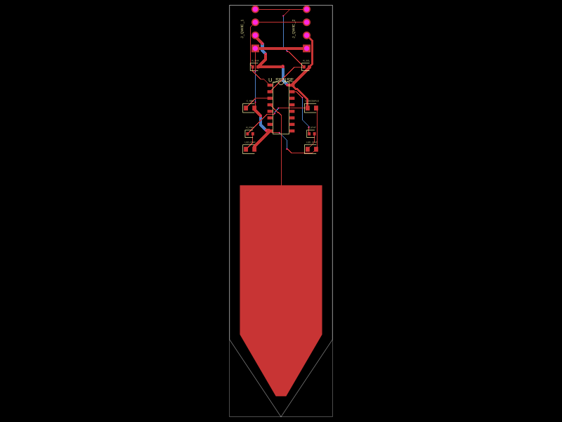 More from this authormohan-bee/soil-finalThis code defines a printed circuit board (PCB) featuring a sensor chip with associated decoupling capacitors, resistors, indicator LEDs with current-limiting resistors, pin headers for external connections, and a custom spear-shaped probe pad.
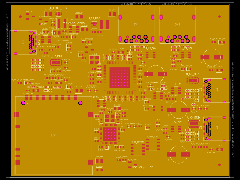 Similar packagegokul/usb3-sd-hubEngineering draft: four-layer, computer-powered USB 3 hub with one USB-C host socket, two USB-C and two USB-A accessory sockets, and a full-size SD slot. Board and three schematic previews are available. Routing and production checks are incomplete; not fabrication ready.
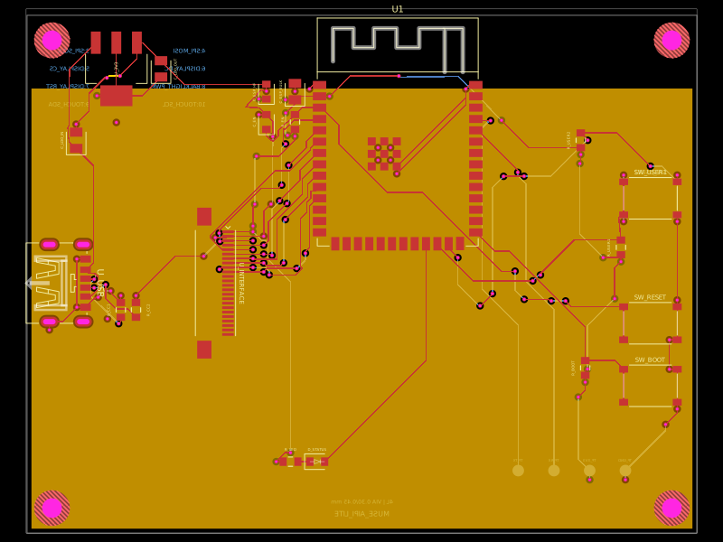 Discover something newShiboSoftwareDev/muse-aipi-lite-replacementA four-layer ESP32-S3 carrier board with USB‑C 5V input, AMS1117 3.3V regulation, FFC display/interface connector, status LED, reset/boot/user buttons, decoupling passives, test points, and ground/power planes.