anil08607/Smartwatch
A 46 mm smartwatch PCB built around an nRF52810 BLE MCU, with USB‑C PD/Li‑ion charging, buck‑boost power, LCD, accelerometer, RTC, buttons, haptic motor, crystals, antenna, and SWD programming connector.
- Version
- 1.0.14
- License
- unset
- Stars
- 0
docs/assembly.md
# Complete product assembly

The compact/exploded models and `mechanical/assembly-manifest.json` cover the complete dimensioned product stack, including separate copper lands and appearance details. They include all 70 fitted PCB component envelopes, board, display, lens, battery, cushion, NTC, motor, harness envelopes, case, bezel, retainer, two plungers, four screws/inserts, two spring bars and two strap halves. This is a provisional packaging model, not supplier-certified CAD or a completed product fit qualification. The default tscircuit entry now exposes every external part as a named subassembly; the exploded entry separates the same parts.

## Datum and space

PCB top is Z=0 mm; PCB bottom is Z=-1 mm. USB faces -X (left); buttons face +X (right), and straps extend along +/-Y. Board: 46 × 46 mm, R8, 1 mm thick. Polymer case: 54 × 54 × 18 mm, excluding lugs and screw-head detail. Screw centers are (±22.8, ±22.8) mm, outside the rounded PCB corners. The PCB has no mounting holes; a lower edge ledge and upper retainer capture it.

The display body is 35.59 × 37.74 × 1.6 mm rotated clockwise in-plane, centred at (0, +3.5) mm, Z=4.4–6.0 mm. The 38 × 40 × 1 mm lens occupies Z=6.2–7.2 mm. A 30 × 35 × 4 mm cell envelope sits below the PCB, leaving a nominal 0.7 mm swelling space above the cushion. The protection circuit, leads and supplier tolerance must fit this envelope; no unprotected cell is approved. The 12 mm motor sits beside the battery. Keep metal, cell foil and harnesses out of the antenna window defined in `hardware-contract.json`.

## Assembly sequence

1. Inspect bare PCB fabrication and the top SMT assembly. Check exact MPNs, pin 1, polarity, solder joints and connector latch direction. Request X-ray for hidden-joint ICs. Do not fit M1 as an SMT component.
2. Perform current-limited PCB bring-up using `docs/bring-up.md`. Program and verify an application built for the documented nRF52810 pin map.
3. Print base, bezel, display retainer and both button plungers. Deburr and dry-fit the PCB. Check the USB opening, button actuation, FPC latch access, screw clearances and the RF window. Confirm exact M2 insert dimensions before fitting inserts.
4. Bond the insulated SEMITEC 103AT-2 NTC to the qualified protected battery pack using materials approved by the pack supplier. Connect it only to J5. Label the NTC harness separately from the battery lead.
5. Install the cushion, battery and motor. Hand-solder motor leads to M1 with power removed. Dress and strain-relieve leads; do not pinch them against the retainer or screws. Verify battery J2 pin 1 is positive and pin 2 is ground with a meter before connection.
6. Connect the no-touch LCD FPC to J4. Confirm contact side, pin 1, latch closure and actual flex bend radius/length using the purchased panel. The model's flex shape is an envelope, not a manufacturing drawing.
7. Install display retainer, display, lens bond and bezel after validating the optical aperture and stack height. Verify insert engagement and screw length physically; no screw may contact the cell or copper.
8. Fit the 22 mm strap and spring bars. Verify retention, button travel and USB access. Repeat charging, thermal, RF, haptic, display and low-power tests in the closed case.

## Remaining mechanical approvals

Exact battery/protection/lead drawing; harness cut lengths; lens and adhesive specification; exact insert selection; plunger travel; case print tolerances; flex folding; enclosure collision inspection; retention/drop/skin-contact and thermal tests. No water-resistance rating is claimed. Purchased strap geometry is illustrative.

## Updated mechanical detail

The display has a perimeter support ledge and a 0.10 mm tape seat, plus a 0.20 mm lens bond. Battery foil, protection tape, label face and separate positive/return leads are visible. The clock face is an illustrative CAD graphic, not running firmware. Existing ER-TFT1.28-3 electrical compatibility and the protected LP403035 pack envelope are retained.

Both captive plungers align with SW1/SW2 at Y=+3.5/-3.5 mm and stem Z=1.7 mm. The pair is centred on the right side; the finger caps are centred at Z=0.5 mm, the midpoint of the 18 mm enclosure. Their stem starts at X=22.68 mm, giving nominal 0.15 mm clearance from the imported actuator envelope. The stem has 0.30 mm clearance per side in the case guide and 0.30 mm available inward travel. An internal flange prevents outward loss; final switch stroke and molding tolerances need physical confirmation.

Battery, thermistor and motor leads pass around the board perimeter instead of crossing its substrate. `docs/checks/mechanical-clearance.json` records actual solid intersections for these routes, display/retainer, battery/motor, button/case at rest and full travel, and the USB cable insertion sweep. These scoped nominal checks do not certify the unknown supplier flex population or the complete tolerance stack.

Browser CAD importers can discard glTF transparency. The clock-face graphic is a cosmetic mesh placed 0.02 mm above the outer lens so it remains visible there. It follows the lens in the exploded view, is not an extra manufactured part, and does not change the specified LCD or physical stack.

## Side USB cable access

The USB-C receptacle is on the left side, opposite the centred button pair. The opening spans 14 mm along Y and 8 mm along Z and continues into the bezel; it admits the cable overmould into the wall recess rather than leaving only a hole for the metal tip. The checked nominal cable body is 20 x 12 x 6 mm, with its seated front at X=-24.5 mm, plus a 6.5 x 8.4 x 2.6 mm metal-tip envelope. The clearance test sweeps both 20 mm outward with both straps and spring bars installed. Cable bodies larger than this envelope need a fresh fit check. Verify full electrical engagement with the chosen cable on the prototype.

The PCB and internal stack turn clockwise together to preserve critical radio/clock paths. SW1/SW2 move to the right-side midpoint; J3 moves to (-7,-18) mm and faces -Y, accessible for service with the case open. The display flex approaches J4 from +Y. The battery is centred at (-2,+6) mm; the motor is at (16,-16.5) mm. All STL/GLB, placements and fabrication exports use these new coordinates.
Related Packages
 More from this authoranil08607/issue1This code defines a schematic diagram of a DS3231MZ real-time clock (RTC) integrated circuit connected to a 3.3V power supply, I2C data lines, and control signals on a PCB.
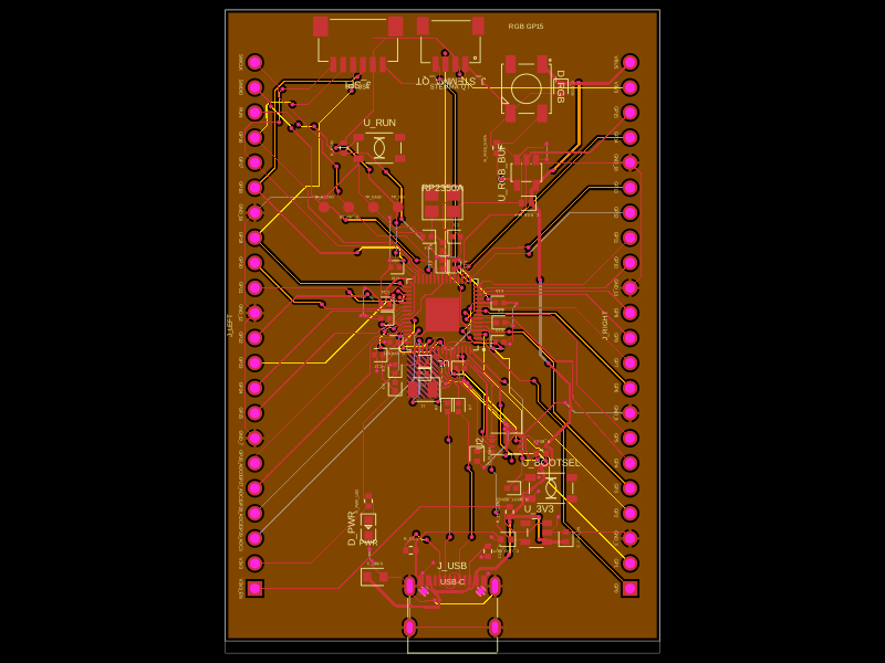 Similar packageabse/rp2350-mcu-boardThis code defines a compact, four-layer PCB hardware layout for the Raspberry Pi RP2350A microcontroller module, including the main IC, power regulation, USB-C connector, STM32-compatible headers, and associated passive components, with detailed component footprints, net connections, and copper pour zones for powering and ground references.
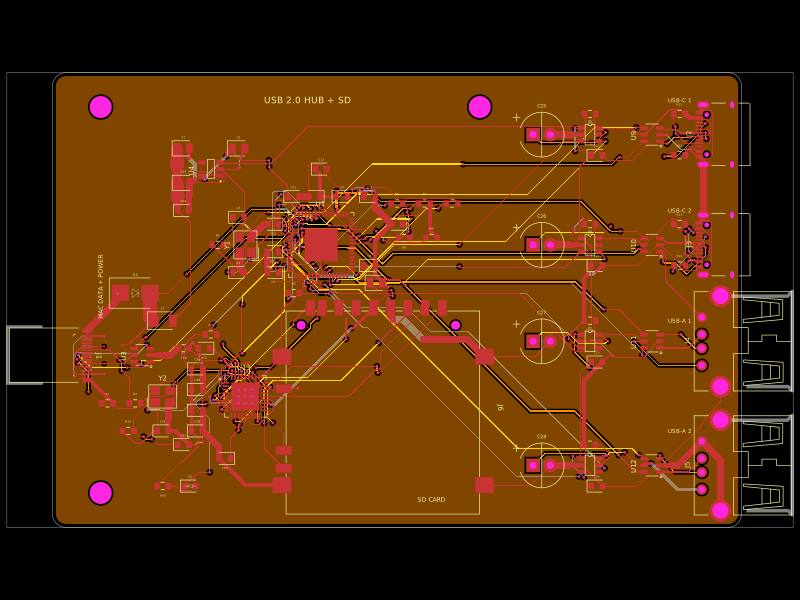 Discover something newgokul/usb-hub-boardA 4-layer 100×66 mm USB 2.0 hub board with a USB‑C upstream port, four protected downstream USB‑C/USB‑A ports, an integrated SD card reader, USB hub controllers, 3.3 V regulation, ESD protection, current-limited power switches, crystal oscillators, and filtering/passive components.