abse/gameboy-advance
Validates and exports a four-layer Game Boy–style PCB assembly with RP2350 MCU, 32MB flash, USB-C, LCD and speaker connectors, battery buck-boost power, buttons, and verified routing, connectivity, clearances, CAD models, and physical DRC.
- Version
- 0.0.39
- License
- unset
- Stars
- 0
ELECTRICAL_PROTOTYPE_REVIEW.txt
PROTOTYPE ELECTRICAL REVIEW — v0.0.39

Corrected design candidate for a small, current-limited bench prototype batch.
This is not production/USB-compliance or physical thermal qualification.

1. Display/MCU shared logic supply is3.23394V nominal using AP63200WU-7,
C2071868, with49.9k +300ohm upper divider and16.5k lower divider. Precision
49.9k/16.5k parts are0.1%,25ppm/C;300ohm trim is1%,100ppm/C. Static supply
bound including65C resistor temperature allowance is3.18878–3.27942V.
The prototype review reserves20mV positive ripple/overshoot below LCD3.30V.
The warmed0.6mm logic feeder,0.5A load allowance,5mV downstream drop and
10mV negative ripple allowance leave RP2350 USB supply>=3.1469V; the20mA
analog-load allowance and warm ferrite DCR leave VREG_AVDD>=3.1447V,
above the manufacturer3.135V minimum. These load/ripple allowances require
bench verification; they are not measured limits or hard current clamps.

2. R_VREG_AVDD now denotes a BLM15PD121SN1D ferrite/C76891, replacing
33ohm. The reference is retained so existing net/pin checks remain explicit.
A0.6mm bottom copper feed connects the actual converter output to the logic
rail; it does not use the feedback pin as a power tap. The AP63200 uses the
shared Diodes TSOT26 land pattern in its canonical pin1-right/bottom orientation:
PCB/CPL rotation0, supplier CAD world rotation180. Verify factory CPL preview.
The3.9uH output inductor remains within the adjustable-regulator ripple-current
selection equations for the5V input,500kHz design. Input10uF and2x22uF output
follow the manufacturer's nominal capacitor table. Effective DC-biased
capacitance, startup, PFM ripple, transient response and ferrite ringing need scope checks.

3. R_SPK_LIMIT is330kohm/C25778 in series after the coupling capacitor and
before PAM8403 INL. It lowers gain without a firmware-only volume limiter.
The conservative continuous-AC calculation, with internal-gain/component
margins, is0.707W into4ohm, or0.353W into the specified8ohm1W speaker.
Turn-on/off pops and actual speaker waveforms still require bench checks.
Neither speaker wire may be grounded. Maximum volume will be lower.

4. Battery inductor is APV APH0420T1R5M/C5349662,1.5uH, approximately
USD0.10. The1.5A battery-converter-output design target produces3.049A
estimated peak at3.2V input with conservative L/f/efficiency assumptions;
20% margin is3.659A, below4.57A lower tabulated saturation. No hardware
1.5A output clamp is added. Verify actual low-battery load and thermal behavior;
this does not qualify unrestricted overload or continuous2A boost operation.

Final native build and independent all-layer Gerber short check pass.
Zero DRC errors, shorts, split nets, trace-length errors, PCB and schematic
style findings.470 physical ports,123 annotated components,11 sheets,
14 manufacturer button-contact checks.23 existing requested-width warnings
remain; they do not replace physical power-path evaluation. Original pin/net
partitions are preserved except the two deliberate feedback/input changes,
which have explicit new-chain and authored-endpoint checks.

All176 changed-component/enclosure envelope checks pass. All56 JLCPCB part
types /119 placements are listed in stock for5boards before attrition; stock
is not reserved. Enclosure hardware/print geometry and USB pair are unchanged.
Use JLC04161H-3313 stackup for the intended90ohm differential geometry.
Inspect JLCPCB CPL polarity/pin1 preview and through-hole shoulder assembly
before payment; automatically exported placement rotation confidence is not complete.

Bring-up: inspect assembled polarity and resistance first, start with a
current-limited bench source and display/speaker disconnected, measure logic
(~3.234V) and core (~1.1V) before attaching peripherals, then check startup,
load/USB handover, current, backlight current, maximum audio and temperature.
The device has no AA charging circuitry. Application firmware and32MB flash
addressing remain implementation/qualification work, not completed firmware.
Related Packages
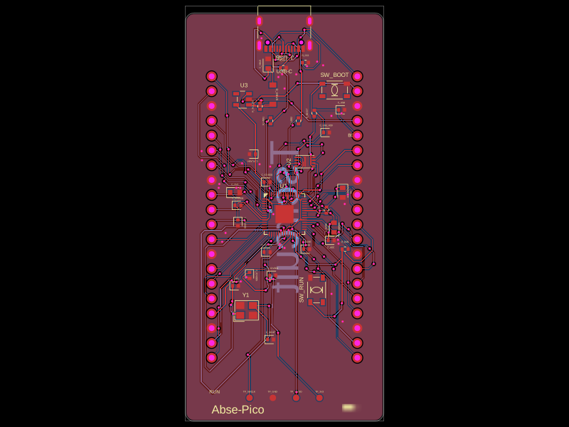 More from this authorabse/abse-picoThis code defines 3D models and footprints for various electronic components—such as voltage regulators, microcontrollers, and memory chips—highlighting their physical pin configurations, mounting pads, and visual identifiers for PCB design.
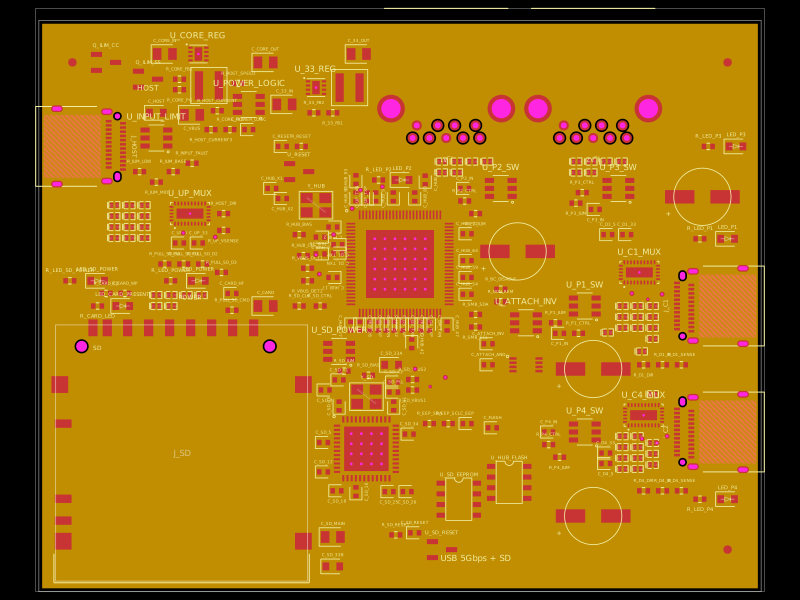 Similar packagegokul/usb3-sd-hubEngineering draft: four-layer, computer-powered USB 3 hub with one USB-C host socket, two USB-C and two USB-A accessory sockets, and a full-size SD slot. Board and three schematic previews are available. Routing and production checks are incomplete; not fabrication ready.
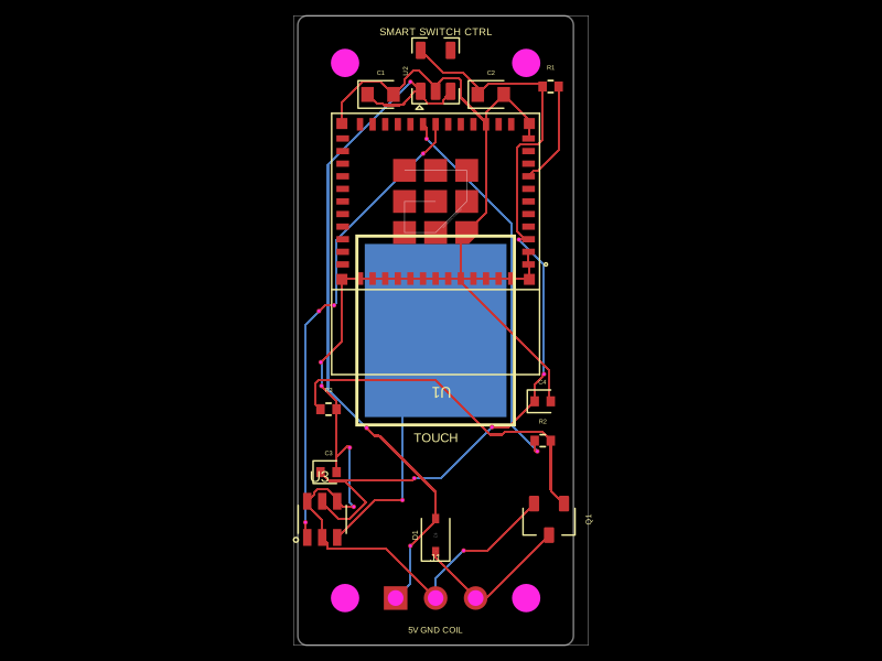 Discover something newhrithik18k/smart-switch-pcbThe AO3400A component models a SOT-23 N-channel MOSFET with labeled pins for Gate, Source, and Drain, including 3D CAD models and schematic symbols for electronic circuit design.