abse/gameboy-advance
Validates and exports a four-layer Game Boy–style PCB assembly with RP2350 MCU, 32MB flash, USB-C, LCD and speaker connectors, battery buck-boost power, buttons, and verified routing, connectivity, clearances, CAD models, and physical DRC.
- Version
- 0.0.39
- License
- unset
- Stars
- 0
ASSEMBLY_GUIDE.md
# R13 assembly

1. Install all 17 heat-set inserts into bare shells: 9 M2, 4 M3, 4 M2.5. Check bores with the coupon. Case blind pilots are 6.5 mm deep for M2.5x16 screws; case insert length remains 4 mm.
2. Seat display and foam; tighten 5 LCD M2x4 screws. Fit speaker and ring with 2 M2x4 screws. Upper display mounts are now (62,39.8) and (69,38) mm. Keep buttons and paddles out while tightening. Tighten gently and evenly on inactive glass borders.
3. With front face down, rear-load all caps. The D-pad has a hidden retaining flange. Fit shoulder pads/paddles after LCD screws: hold the paddle 0.7 mm outward, slide up 6 mm through the concealed lead-in, then slide inward. Enlarged shoulder faces cover their front openings; rear slots remain closed.
4. Seat holder in rear cradle with the open cell side toward the battery door. Fit two keepers with M2x5 screws into rear-shell inserts. Prepare PH harness and verify polarity. No holder load goes into the PCB.
5. Place four nylon washers (3.2 mm ID, 7 mm OD, 0.5 mm thick) under the M3x6 pan-head screws. Fit PCB in rear shell and tighten from the open front side. Keep the front assembly supported separately. Connect battery, speaker and display FPC before closing. Do not bend the driver or stiffened tail; production flex radius and the connection-stage route require physical qualification.
6. Check cap return, folded flex and lead restraint; mate shells. Fit four M2.5x16 screws from rear access bores into front-shell inserts. Check current-limited power and low-volume audio. Install four AA cells through the rear opening last, then locate door tongues and engage the plastic latch.

Hardware: 7 M2x4, 2 M2x5 ISO7046 Type-H countersunk Phillips screws (PH0); 4 M3x6 ISO7045 pan-head screws (PH1); 4 M2.5x16 ISO7046 Type-H screws (PH1). Four nylon PCB washers. Use PH0 shaft <=3 mm and PH1 shaft <=4 mm; a slender 3 mm heat-set tool neck was checked. Screw drive geometry is a simplified standard reference; threads are omitted. Buy actual cross-recessed hardware to these specifications.

Verification: 43 tool/insertion checks, 17 screw/insert pairs, 55 fastener checks, 37 latch/shoulder checks, 78 face-button checks, 17 connected watertight print bodies, zero component-fit findings. Physical fit testing remains required.

[CAD PDF](https://registry-api.tscircuit.com/package_files/download?package_file_id=450a500e-383b-4b3d-8862-4eeca354b14f) | [Diagram PNG](https://registry-api.tscircuit.com/package_files/download?package_file_id=78d7aeed-cbde-462a-ad2b-415ded2b9988) | [Print pack](https://registry-api.tscircuit.com/package_files/download?package_file_id=731d4c1b-571c-493b-ad41-3ad9b07c3b23)

Current corrected-control assembly diagram: https://registry-api.tscircuit.com/package_files/download?package_file_id=a98a15d5-467a-4f45-b484-802f97d35a65
Current front-shell print pack: https://registry-api.tscircuit.com/package_files/download?package_file_id=2c65aa5d-486e-426b-b658-b19df225c06c
Related Packages
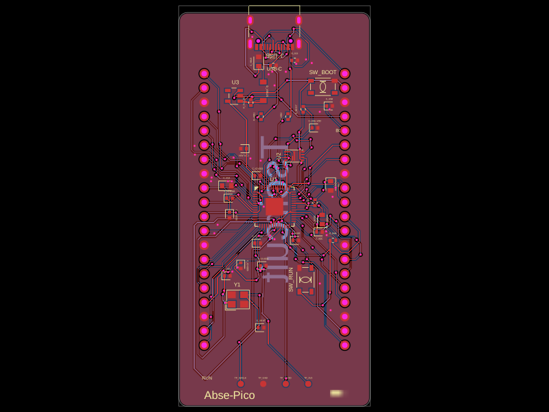 More from this authorabse/abse-picoThis code defines 3D models and footprints for various electronic components—such as voltage regulators, microcontrollers, and memory chips—highlighting their physical pin configurations, mounting pads, and visual identifiers for PCB design.
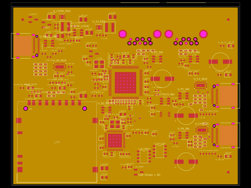 Similar packagegokul/usb3-sd-hubEngineering draft: four-layer, computer-powered USB 3 hub with one USB-C host socket, two USB-C and two USB-A accessory sockets, and a full-size SD slot. Board and three schematic previews are available. Routing and production checks are incomplete; not fabrication ready.
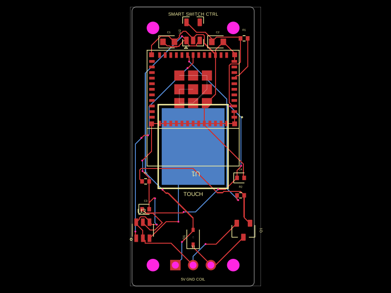 Discover something newhrithik18k/smart-switch-pcbThe AO3400A component models a SOT-23 N-channel MOSFET with labeled pins for Gate, Source, and Drain, including 3D CAD models and schematic symbols for electronic circuit design.