ShiboSoftwareDev/linux-gameboy-advance
A multilayer PCB carrier/router with USB-C and battery power selection, buck regulation, microSD, LCD/backlight, UART/SPI/I²C service headers, controls, volume input, and RGB status LEDs, using vias and reviewed copper routing.
- Version
- 1.0.123
- License
- unset
- Stars
- 0
POWER-REVISION.md
# Power corrections, revision 1.0.100

- The removable battery source is now two AA cells in series, matching the original GBA's battery count. The board is labelled `2xAA 1.8-3.2V • NO CHARGE`; USB never charges the cells.
- `U_BUCK_3V3` is a TI TPS63020DSJR buck-boost converter (JLCPCB `C15483`). Unlike the former AP63203 buck, it can maintain 3.3 V while a two-cell pack is both below and above the output voltage.
- `L_BUCK_3V3` is a shielded 1.5 µH YHNR4020-1R5M (JLCPCB `C18199423`, 5.2 A rated / 7.7 A saturation). The input and output networks use two 10 µF input ceramics and three 22 µF output ceramics around the compact switching loop.
- The battery path uses an AO3401A P-channel MOSFET (JLCPCB `C347476`) controlled from USB VBUS. With USB absent, the gate pull-down enables the battery; with USB present, the gate is raised and isolates it. This avoids spending the limited two-AA voltage in a series Schottky diode.
- The long battery, selected-input, SYS_IN and 3V3 trunks are physically 0.50 mm wide. Only the necessary TPS63020 DSJ 0.5 mm-pitch escapes neck to the 0.12 mm fabrication minimum.
- The existing resettable fuse and hard power switch remain in the battery path. `J_USB` remains the single USB-C receptacle for both USB2/FEL data and default 5 V input.
- `U_2V5` remains the AP2112K-2.5TRG1 DDR1 rail (`C176945`), `U_1V2` remains the core rail, and `U_2V8` remains the AP2127K-2.8TRG1 analog rail (`C460327`).
- The AP3031 boost/current driver and two series 1 Ω sense resistors regulate the LCD backlight to approximately 100 mA (`0.2 V / 2 Ω`).
- The reviewed V3V3 transition-via clearance repair and the exact 0.30 mm finished-hole / 0.45 mm pad via rules remain enforced by `verify.mjs`.

Mechanical integration:

- The former external-holder pod is removed. A continuous enclosure base leaves a 32 × 54.5 × 14.5 mm bay beneath the PCB for two 14.5 × 50.5 mm maximum-envelope AA cells, internal series contacts and insulated wiring to `J_BAT`.
- A separate flush PETG door is 36.4 × 58.8 × 1.2 mm, seats in a 37 × 59.4 mm rebate, and closes a 33.6 × 56 mm rear opening with an inner tongue, insertion tab, flex latch and thumb dimple.
- The PCB cable slot is retained only to pass the internal contact lead to top-side `J_BAT`; the enclosure has no battery-cable opening.

Sources:

- TI TPS63020 product page and datasheet: https://www.ti.com/product/TPS63020
- Energizer AA maximum dimensions: https://data.energizer.com/pdfs/nh15-2500.pdf
- Allwinner F1C100S datasheet: https://linux-sunxi.org/images/b/ba/F1C100s_Datasheet_V1.0.pdf
- AP2112: https://www.diodes.com/datasheet/download/AP2112.pdf
- AP2127: https://www.diodes.com/datasheet/download/AP2127.pdf
- AP3031: https://datasheet.lcsc.com/lcsc/1811081712_Diodes-Incorporated-AP3031KTR-G1_C82636.pdf
- ER-TFT035IPS-6: https://www.buydisplay.com/download/manual/ER-TFT035IPS-6_Datasheet.pdf

This revision is software-checked but not physically qualified. Before production, prototype and measure two-AA cold-start behavior, rail transients, peak-load brownout margin, regulator and inductor temperature, USB source handover, AA-contact resistance, door retention, and the fabricator's final stackup.
Related Packages
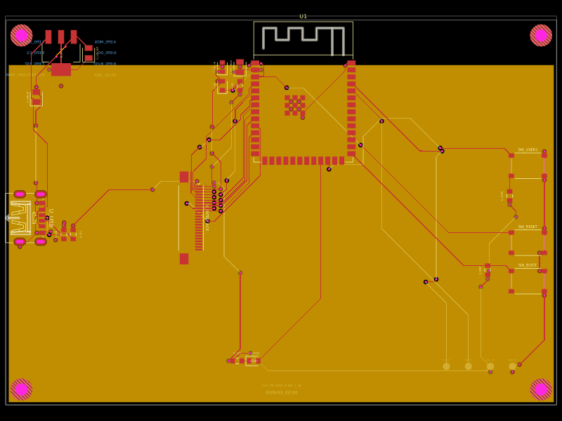 More from this authorShiboSoftwareDev/muse-reterminal-e1001-replacementA four-layer ESP32-S3 e-paper carrier board with USB-C power, AMS1117 3.3V regulation, 24-pin FFC interface, reset/boot and user buttons, status LED, decoupling passives, test points, mounting holes, and ground/power planes.
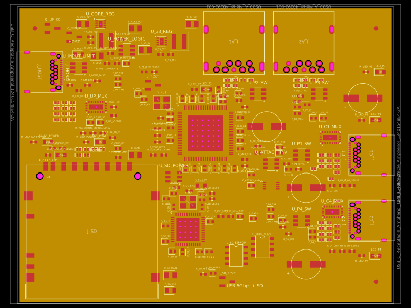 Similar packagegokul/usb3-sd-hubEngineering draft: four-layer, computer-powered USB 3 hub with one USB-C host socket, two USB-C and two USB-A accessory sockets, and a full-size SD slot. Board and three schematic previews are available. Routing and production checks are incomplete; not fabrication ready.
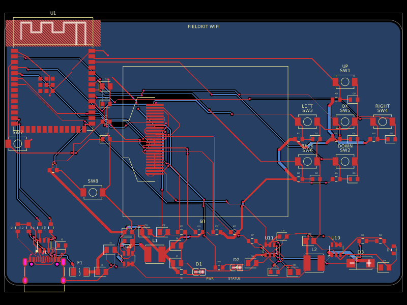 Discover something newgokul/fieldkit-usbUSB-C-powered ESP32-S3 Wi-Fi/Bluetooth handheld with an SMD 128x32 OLED, six navigation buttons, USB-C power/data, complete checked routing, and four native schematic sheets.