MustafaMulla29/breakoutpoints
This design features a 20mm by 16mm custom PCB with a 16-pin QFP microcontroller (U1), a 100nF capacitor (C1), a 4-pin pin header (J1) for power and I²C connections, and a 10kΩ resistor (R1) connecting the microcontroller reset to VCC.
- Version
- 0.0.1
- License
- unset
- Stars
- 0
index.tsx
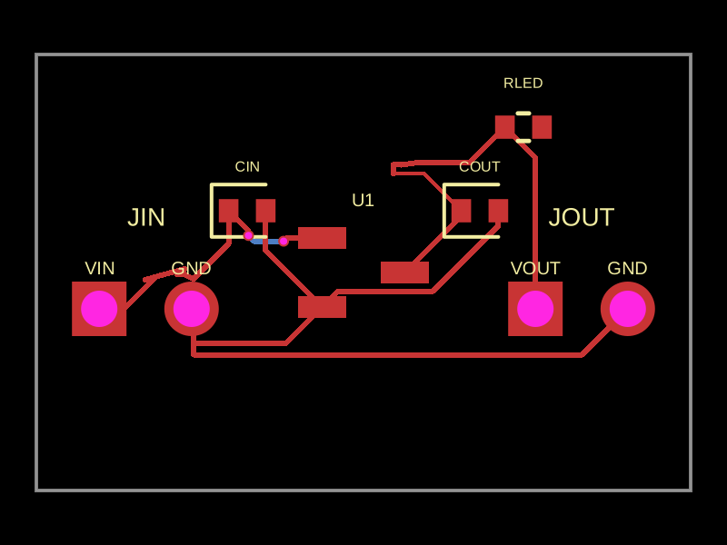
PCB
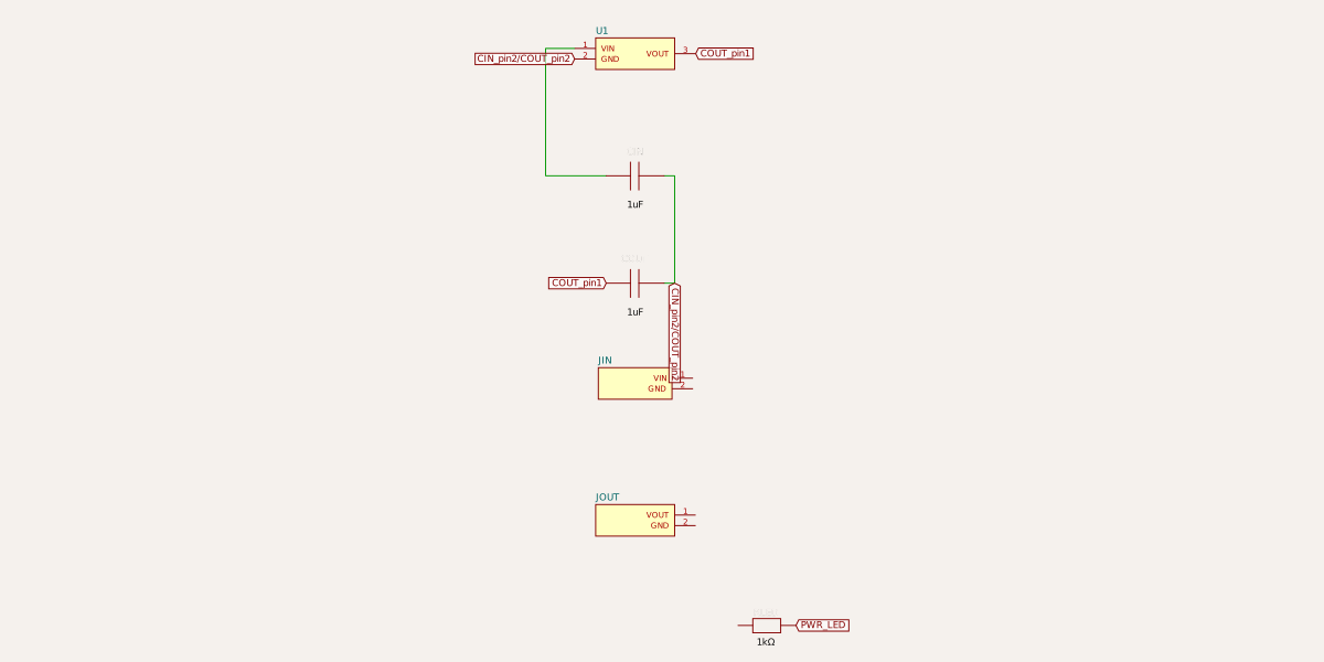
Schematic
export default () => (
  <board width="18mm" height="12mm">
      <breakout name="REG_BREAKOUT" padding="0.7mm">
        <chip
          name="U1"
          footprint="sot23"
          pinLabels={{
            pin1: "VIN",
            pin2: "GND",
            pin3: "VOUT",
          }}
          pcbX={0}
          pcbY={0}
        />
        <capacitor
          name="CIN"
          capacitance="1uF"
          footprint="0402"
          pcbX={-3.2}
          pcbY={1.7}
          connections={{ pin1: "U1.VIN", pin2: "U1.GND" }}
        />
        <capacitor
          name="COUT"
          capacitance="1uF"
          footprint="0402"
          pcbX={3.2}
          pcbY={1.7}
          connections={{ pin1: "U1.VOUT", pin2: "U1.GND" }}
        />
      </breakout>
      <pinheader
        name="JIN"
        pinCount={2}
        footprint="pinrow2"
        pinLabels={["VIN", "GND"]}
        pcbX={-6}
        pcbY={-1}
      />
      <pinheader
        name="JOUT"
        pinCount={2}
        footprint="pinrow2"
        pinLabels={["VOUT", "GND"]}
        pcbX={6}
        pcbY={-1}
      />
      <resistor
        name="RLED"
        resistance="1k"
        footprint="0402"
        pcbX={4.4}
        pcbY={4}
        connections={{ pin1: "U1.VOUT", pin2: "net.PWR_LED" }}
      />
      <trace from="JIN.VIN" to="U1.VIN" />
      <trace from="JIN.GND" to="U1.GND" />
      <trace from="JOUT.VOUT" to="U1.VOUT" />
      <trace from="JOUT.GND" to="U1.GND" />
    </board>
)