AnasSarkiz/magnetic-shutter-remote-r8
A USB‑C rechargeable battery-powered ESP32‑C3 wireless controller with Li‑ion charging, protected 3.3‑V buck‑boost regulation, thermal/safety monitoring, status LEDs, buttons, programming UART, crystal clock, and 2.4‑GHz antenna matching network.
- Version
- 0.4.0-prototype
- License
- unset
- Stars
- 0
src/schematic-component-notes.tsx
import { Fragment } from "react";

// Native annotations only; electronic parts remain qualified JLCPCB imports.
// Each row: reference, role, and two short lines explaining its purpose.
export const componentNotesBySheet = {
	Power: [
		[
			"J1",
			"USB-C charge input",
			"Accepts 5 V for charging only.",
			"USB present holds the radio power off.",
		],
		[
			"R1",
			"5.1k CC1 pull-down",
			"Identifies a USB-C power sink on CC1.",
			"Allows either cable orientation with R2.",
		],
		[
			"R2",
			"5.1k CC2 pull-down",
			"Identifies a USB-C power sink on CC2.",
			"Allows either cable orientation with R1.",
		],
		[
			"U2",
			"BQ25185 Li-ion charger",
			"Charges the cell at nominal 300 mA.",
			"Manages USB input and the SYS power path.",
		],
		[
			"R3",
			"1k charge-current setting",
			"Programs U2 ISET for nominal 300 mA.",
			"Actual current has component tolerance.",
		],
		[
			"C1",
			"4.7uF USB input bypass",
			"Filters USB5V at the charger input.",
			"Supplies brief input-current changes.",
		],
		[
			"C2",
			"4.7uF battery bypass",
			"Filters VBAT at the charger BAT pin.",
			"Supports stable battery charging.",
		],
		[
			"J2",
			"Protected battery connection",
			"Pin 1 is GND; pin 2 is battery positive.",
			"Use the qualified protected-cell pack.",
		],
		[
			"R4",
			"1k charge-LED resistor",
			"Limits current through red LED1.",
			"Connects VBAT to the LED anode path.",
		],
		[
			"LED1",
			"Charge-status indicator",
			"Lights when U2 pulls CHARGE_STAT low.",
			"Indicates charger status, not BLE status.",
		],
		[
			"R8",
			"130k charger VSET setting",
			"Selects the nominal 4.1 V charge target.",
			"Sets U2's combined VSET / ILIM mode.",
		],
		[
			"R9",
			"10k charger TS bias",
			"Provides the fixed bias on U2 TS input.",
			"U5 supplies the separate temperature gate.",
		],
		[
			"C8",
			"10uF SYS output bypass",
			"Decouples the charger's SYS output.",
			"The radio regulator uses VBAT, not SYS.",
		],
		[
			"C9",
			"47pF ISET-node filter",
			"Filters noise at the PROG / ISET node.",
			"Works with charge-setting resistor R3.",
		],
	],
	Radio: [
		[
			"SW2",
			"Side-actuated shutter button",
			"Press grounds SHUTTER on GPIO4.",
			"Firmware sends a BLE Volume-Up keypress.",
		],
		[
			"SW3",
			"Pairing button",
			"Press grounds PAIR on GPIO5.",
			"Hold for 3 seconds to request pairing.",
		],
		[
			"R7",
			"1k status-LED resistor",
			"Limits current from GPIO6 into LED2.",
			"Protects the LED and GPIO output.",
		],
		[
			"LED2",
			"BLE status indicator",
			"Firmware controls this red LED via GPIO6.",
			"Shows pairing / connection activity.",
		],
		[
			"J3",
			"Three-pin JST UART",
			"1: RX GPIO20; 2: GND; 3: TX GPIO21.",
			"3.3 V signals; no target-power pin.",
		],
		[
			"SW4",
			"Manual BOOT button",
			"Grounds GPIO9 for ROM download mode.",
			"Hold BOOT while pressing / releasing RESET.",
		],
		[
			"SW5",
			"Manual RESET button",
			"Grounds chip EN to reset the ESP32-C3.",
			"Release after selecting normal / BOOT mode.",
		],
	],
	RadioCore: [
		[
			"U1",
			"Bare ESP32-C3FH4",
			"Runs BLE shutter firmware; 4 MB in-package flash.",
			"QFN chip; clock and RF support are external.",
		],
		[
			"L2",
			"2 nH radio supply filter",
			"Feeds pins 2/3 through the radio LC filter.",
			"Rated 900 mA; C5/C10 bypass its output.",
		],
		[
			"C5",
			"100 nF RF supply bypass",
			"Local bypass for U1 VDD3P3 pins 2/3.",
			"Connects RADIO_3V3 to GND.",
		],
		[
			"C10",
			"10 uF radio bulk bypass",
			"Supports radio current bursts after L2.",
			"Effective capacitance requires bias review.",
		],
		[
			"C14",
			"100 nF RTC supply bypass",
			"Bypasses U1 RTC power pin 11.",
			"Keep its return short to the ground plane.",
		],
		[
			"C15",
			"100 nF CPU supply bypass",
			"Bypasses U1 CPU power pin 17.",
			"Keep its return short to the ground plane.",
		],
		[
			"C16",
			"1 uF internal flash rail bypass",
			"Decouples U1 VDD_SPI output pin 18.",
			"Do not connect this output directly to 3V3.",
		],
		[
			"C17",
			"1 uF analog rail bypass",
			"Bypasses U1 VDDA pins 31/32.",
			"Pairs with high-frequency bypass C18.",
		],
		[
			"C18",
			"10 nF analog rail bypass",
			"Shunts fast noise at U1 VDDA pins 31/32.",
			"Keep adjacent to the analog supply pins.",
		],
		[
			"R14",
			"GPIO2 boot strap pull-up",
			"Pulls GPIO2 high during reset.",
			"10k; GPIO2 is not used as a user control.",
		],
		[
			"R15",
			"GPIO8 boot strap pull-up",
			"Holds GPIO8 high for ROM UART download.",
			"10k; GPIO9 is selected by BOOT switch.",
		],
		[
			"R16",
			"GPIO9 boot strap pull-up",
			"Selects normal boot when BOOT is released.",
			"Hold BOOT low during RESET for flashing.",
		],
		[
			"Y1",
			"40 MHz crystal",
			"External main clock; nominal load 15 pF.",
			"Ground both case pads; frequency test pending.",
		],
		[
			"L3",
			"24 nH crystal harmonic filter",
			"Series component between XTAL_P and Y1.",
			"Initial value from Espressif; tune on hardware.",
		],
		[
			"C19",
			"27 pF crystal load",
			"Loads the XTAL_P crystal terminal to GND.",
			"27p pair assumes 1.5p stray for 15p load.",
		],
		[
			"C20",
			"27 pF crystal load",
			"Loads the XTAL_N crystal terminal to GND.",
			"Frequency must be measured before approval.",
		],
		[
			"C21",
			"1.5 pF chip RF match",
			"Chip-side shunt in Espressif C-L-C network.",
			"Initial value; physical RF tuning pending.",
		],
		[
			"L4",
			"2 nH chip RF match",
			"Series inductor between chip and 50 ohm feed.",
			"Initial value; physical RF tuning pending.",
		],
		[
			"C22",
			"1.5 pF antenna-side RF match",
			"Shunt after L4 in the chip matching network.",
			"Ground return must be short on the RF plane.",
		],
		[
			"ANT1",
			"2.4 GHz ceramic antenna",
			"Pin 1 is RF feed; pin 2 is solder support.",
			"Keep pin 2 unconnected and all-layer clearance.",
		],
		[
			"R17",
			"10k EN pull-up",
			"Pulls CHIP_EN up to start the bare chip.",
			"C23 delays startup; RESET grounds this node.",
		],
		[
			"C23",
			"1uF EN delay",
			"10k/1uF gives nominal 10ms reset RC.",
			"Replaces reset support previously in module.",
		],
	],
	Protection: [
		[
			"SW1",
			"Radio ON / OFF slide switch",
			"ON feeds BATTERY_OK through R5 to enable.",
			"OFF grounds that path; charging still works.",
		],
		[
			"R5",
			"100k enable-feed resistor",
			"Feeds REG_EN from the power-switch output.",
			"Lets Q1 override enable when USB is present.",
		],
		[
			"Q1",
			"USB-present radio disable",
			"USB5V turns this 2N7002 MOSFET on.",
			"Pulls REG_EN low, disabling radio power.",
		],
		[
			"R6",
			"100k USB / gate pull-down",
			"Bleeds USB5V when the cable is removed.",
			"Keeps Q1 gate low without USB input.",
		],
		[
			"U3",
			"TPS63031 buck-boost regulator",
			"Regulates the battery to fixed 3.3 V.",
			"Runs only when REG_EN permits radio power.",
		],
		[
			"L1",
			"1.5uH switching inductor",
			"Transfers energy between U3 switch nodes.",
			"Rating includes +/-30% inductance tolerance.",
		],
		[
			"C3",
			"10uF regulator input bypass",
			"Supplies switching current on VBAT.",
			"Works with input bulk capacitor C11.",
		],
		[
			"C11",
			"10uF regulator input bulk",
			"Adds battery-side energy storage for U3.",
			"Complements C3 at the power input.",
		],
		[
			"C13",
			"100nF regulator input bypass",
			"Filters fast noise at U3's VBAT input.",
			"Complements the larger input capacitors.",
		],
		[
			"C4",
			"10uF regulator output bypass",
			"Smooths the regulated 3.3 V supply.",
			"Works with output capacitor C12.",
		],
		[
			"C12",
			"10uF regulator output bulk",
			"Adds output storage for load transients.",
			"Complements C4 on the 3.3 V rail.",
		],
		[
			"U4",
			"TPS3839 low-battery supervisor",
			"Monitors VBAT; nominal threshold 3.08 V.",
			"Drives BATTERY_OK low below that threshold.",
		],
		[
			"C6",
			"100nF supervisor bypass",
			"Decouples U4's battery supply locally.",
			"Reduces fast noise at the supervisor.",
		],
		[
			"U5",
			"TMP390 temperature gate",
			"Allows charging inside the set window.",
			"Must be thermally coupled to the cell.",
		],
		[
			"C7",
			"100nF temperature-IC bypass",
			"Decouples USB5V at U5 supply pin.",
			"Filters supply noise for the comparators.",
		],
		[
			"R10",
			"1.62k hot-limit setting",
			"Sets U5's nominal hot limit near 36 C.",
			"Charging is disabled above this limit.",
		],
		[
			"R11",
			"18.7k cold-limit setting",
			"Sets U5's nominal cold limit near 5 C.",
			"Charging is disabled below this limit.",
		],
		[
			"R12",
			"100k TEMP_OK pull-up",
			"Pulls U5's open-drain outputs high.",
			"TEMP_OK falls low outside the safe window.",
		],
		[
			"R13",
			"100k charge-disable pull-up",
			"Pulls U2's active-low charge enable high.",
			"Defaults charging off when Q2 is off.",
		],
		[
			"Q2",
			"Temperature-to-charge gate",
			"TEMP_OK high turns this 2N7002 on.",
			"Pulls CHARGE_DISABLE low to allow charging.",
		],
	],
} as const;

export type CircuitSheetName = keyof typeof componentNotesBySheet;

export function SchematicComponentNotes({
	sheet,
}: {
	sheet: CircuitSheetName;
}) {
	return (
		<>
			{componentNotesBySheet[sheet].map(
				([reference, , firstLine, secondLine], index) => {
					const schY = 9.5 - index * 0.85;
					return (
						<Fragment key={reference}>
							<schematictext
								text={`${reference}: ${firstLine}`}
								schX={-15.5}
								schY={schY}
								anchor="left"
								fontSize={0.23}
							/>
							<schematictext
								text={secondLine}
								schX={-15.5}
								schY={schY - 0.36}
								anchor="left"
								fontSize={0.23}
							/>
						</Fragment>
					);
				},
			)}
			{sheet === "Radio" && (
				<>
					<schematictext
						text="J3 programming: battery ON; USB-C unplugged."
						schX={-15.5}
						schY={-0.8}
						anchor="left"
						fontSize={0.23}
					/>
					<schematictext
						text="Programmer J5: straight-through cable; manual BOOT / RESET."
						schX={-15.5}
						schY={-1.22}
						anchor="left"
						fontSize={0.23}
					/>
				</>
			)}
		</>
	);
}
Related Packages
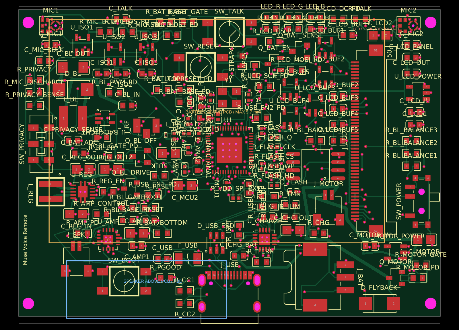 More from this authorAnasSarkiz/muse-voice-remoteMuse Voice Remote v1.3.0: checked prototype PCB/PCBA handoff. Bare ESP32-S3R8 chip, 155 TOP parts from 56 stocked JLCPCB imports with supplier CAD retained. Exact ER-TFT028A2-4 no-touch LCD, dual microphones, TALK, physical privacy, Wi-Fi, speaker, haptic and USB-C. Includes circuit.json, Gerbers/drills, JLC BOM/CPL, segmented stencil artwork and 19 filled/capped thermal-hole map. Native/factory DRC clean; 20 tests pass. See manufacturing/FABRICATION-NOTES.md for stackup and assembly requirements. Physical device/enclosure/RF qualification, firmware and connected-service MUSE integration remain unverified.
 Similar packageaura/diy-power-delivery-triggerThis hardware design implements a USB Type-C port with supporting power management and signal conditioning components, including a USB-C connector, a FUSB302 USB-C port controller, ESD protection diodes, a buck converter for 3.3V power regulation, an STM32 microcontroller for control and processing, an RGB LED indicator, push button, terminal block connections, and associated filtering and support components.
 Discover something newseveibar/am3352-ram-dogbone-and-single-layer-route-testAM3352BZCZ100 processor connected to a W631GG6MB-12 DDR3 memory chip through a routed, length-matched 16-bit DDR interface with clock/data-strobe pairs and control/address signals.